Kenco Engineering SmartSonic Transmitter (Remote) User Manual
Page 6
Page 6
Wiring Connections
In order to connect the wiring, remove the ribbed faceplate on the front of the electronics, using a 7/64” (3mm) Allen
wrench. Ensure that the cover is reinstalled, with the gasket in place, after completing the wiring. Refer to the drawing on
the previous page for the location of the wiring connections and cable entries.
NOTE: Power must be off when wiring the electronics. Damage and/or injury may occur if power is applied
during wiring.
Wiring the Sensor Connections
The sensor uses a custom 5-conductor cable between the sensor and electronics. The cable comes with a cable
connector, which can be used to extend the length of the cable. Make sure that you use Helukabel p/n 16028. Use of
any other cable may damage the sensor, or interfere with the signal.
If you are only using the standard 16.4 ft. of cable supplied attached to the sensor, or the non-connector end of an
extended cable:
1.) Remove the cable connector from the sensor-side of the cable (the male plug). Skip this step if you are using the
non-connector end of an extended cable.
2.) Thread the cable through aperture (C1 – see wiring drawing on page 5) located on the right side of the SmartSonic
electronics base.
3.) Connect each wire by color, to the appropriate screw terminal on connector JP5. If the cable contains multiple black
wires, connect as follows:
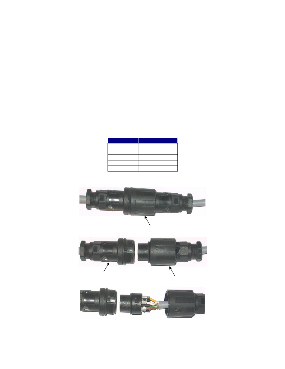
If you are using the cable connector, follow these directions:
1.) Unscrew the nut holding the cable connector together.
2.) Disassemble the “loose cable side” of the connector.
3.) Disconnect the “dummy cable” wires from the connector, and connect the wires from the extended cable (supplied
separately). The blue wire is connected to the cable shield. Make sure that the wires match exactly. If you aren’t
sure, disassemble the “Sensor cable side” connector and match up the pins to the wire color. If you have any
questions, please contact Kenco. Do not apply power unless the connector is wired correctly.
JP5 Post
Color
1
Green (Black 1)
2
Brown (Black 2)
3
Blue (Shield)
4
White (Black 3)
5
Yellow
Nut
Loose cable side
Sensor cable side