Kenco Engineering 512 (old style) User Manual
Kenco engineering company
KENCO ENGINEERING COMPANY
P.O. BOX 470426 TULSA, OK 74147-0426
PHONE(918) 663-4406 FAX: (918) 663-4480
www.kenco-eng.com
e-mail:[email protected]
INSTALLATION INSTRUCTIONS FOR MODEL 512 OIL LEVEL CONTROLLERS WITH ADAPTERS
Note: For fire safe oil level controllers (512-FS) see additional instructions in this work sheet covering installation of fire safe valves.
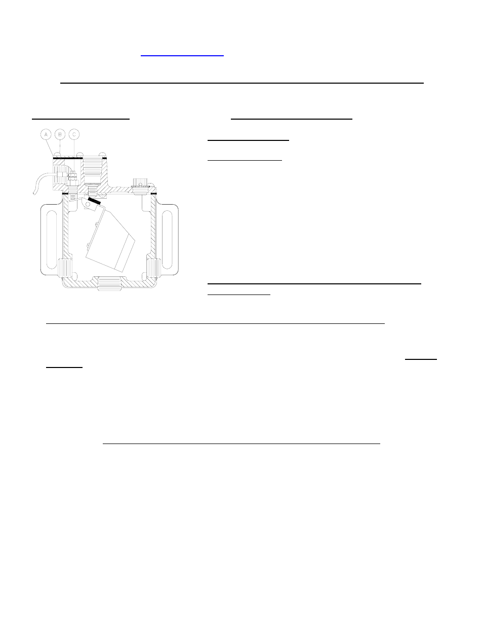
Figure 1- Side View of 512
I.
SWITCH
SPECIFICATIONS
II. INSTALLATION AND MAINTENANCE INSTRUCTIONS FOR OIL INLET VALVE:
•
Connect the oil supply line to the oil inlet on the oil level controller. The minimum recommended supply line is ¾” I.D. The supply
line must be clean and it is recommended that it be flushed with solvent before installation.
•
It is recommended that the oil supply line is connected using hose barb or tube fittings, using a reliable thread sealant. Do not use
Teflon tape.
•
Connect the oil supply line to the oil supply tank. If there is no existing valve at the tank or the existing supply outlet, a shut-off valve
should be placed in the line to prevent oil loss when cleaning the inlet screen or filter.
•
The oil inlet valve is adjusted to maintain the oil level at the center of the sight glass. Low or high levels are often caused by two
problems:
1. Excessive oil inlet pressure, which will cause the unit to overfill.
2. Improper equalizing lines between the crankcase and the controller will also result in improper levels.
Note: 512 models require a minimum of 2’ of head pressure and a maximum of 12’ of oil inlet head pressure.
III. INSTALLATION INSTRUCTIONS FOR UNITS WITH ADAPTERS:
OIL LEVEL CONTROLLERS WITH
–1
(Clark MA & CFA)
–2
(Clark HMB & TMB),
-3
(Clark RA, HRA, HBA, HCA, HLA, TLA),
-
6
(Cooper-Bessemer GMW),
-7
(Cooper-Bessemer GMV),
-8
(Cooper-Bessemer GMX),
-16 , -16-R, -16-6.25
(Cooper-Bessemer BMV
& 275) AND FS OPTIONS
•
Remove the visual oil gauge assembly from the engine and replace it with the oil level controller and adapter assembly supplied with
a gasket and mounting bolts when applicable.
OIL LEVEL CONTROLLERS WITH
–4
(Ingersoll-Rand SVG & KVS),
-5
(Ingersoll-Rand KVG) AND FS OPTIONS
•
Remove the visual oil gauge assembly from the engine and replace it with the oil level controller and adapter assembly supplied with
a gasket and mounting bolts.
•
If the visual oil gauge was vented back to the engine crankcase, remove the vent from the top of the adapter and tie it back to the
crankcase with tubing.
Note: It is important to ensure that there are no loops in this line for it must be trap free and self draining.
Switch Specifications: Case to Ground: 2 AMP, 30 VAC/VDC
Switch Adjustment: Switch adjustment is not recommended.
Improper setting may result in damage to engine. Switch is
factory set at ½” drop. If adjustment for the application is
necessary, refer to figure 1 and follow these instructions:
• Remove the cover of the condulet housing (A) by
unscrewing the 6 screws(B).
• Rotate the slotted set screw(C) counter-clockwise to lower
the switch trip point 3/16”.
• Rotate the slotted set screw(C) clockwise to raise the
switch trip point to a maximum of ½”.
• Attach the wire from the controller to the low tension
terminal on the magneto.
NOTE: The switch is not factory adjusted for proper
shutdown level.