Bird Technologies 73-67-25 Series User Manual
Page 9
TX RX Systems Inc. Manual 7-9120-5 07/26/10 Page 3
Table 2: General specifications for 10” cavity systems.
Frequency Range (MHz)
406 - 512 MHz
Cavity Type and Diameter
3/4-wave, 10” (254 mm)
Maximum Continuous Transmit Power
150 Watt
Isolator Load Power (Continuous)
5W/25W [Note 3]
Minimum TX-TX Separation at Cavity Loss
150 KHz @ -1.5 dB ; 75 KHz @ -2.5 dB
Typical TX-TX Isolation at Minimum Separation (dB)
80 dB
Typical Antenna - TX Isolation (dB)
70 dB
Typical TX Noise Suppression
Depends on cavity loss
Nominal Impedance (Ohms)
50
Maximum Input Return Loss (VSWR)
-20 dB (1.22 : 1)
Temperature Range (°C)
-30 to +60
Connectors, Input and Antenna
N
Mounting
Peg Rack ®
Mounting Options
MC: 19” rackmount adapter plates, 17.5 “ high
LR: System supplied without Peg Rack ® [Notes 4,5]
Maximum Channels / Rack
12 [Note 4]
Dimensions
79.5” x 24” x 36” (H x W x D) [Note 6] ; (2019 x 610 x 914 mm)
Weight - Basic Single-Channel [lb (Kg)]
14 (18.6)
Weight - Expansion Channel Assembly [lb (Kg)]
19 (8.6)
Note 1: -nn in model number represents the number of channels.
Note 2: These specifications are applicable to 406 - 512 MHz models.
Note 3: Models available with 5W/60W loads. same specifications as 25W and 100W models, except load power.
Note 4: -MC option reduces maximum number of channels to ten 10-inch or twelve 6.625-inch channels per rack.
Note 5: -LR systems are tuned and tested on customer frequencies, then disassembled for shipping.
Note 6: Rack depth with cavity tuning rods at maximum frequency. Rod travel is approximately 5.1” (130 mm).
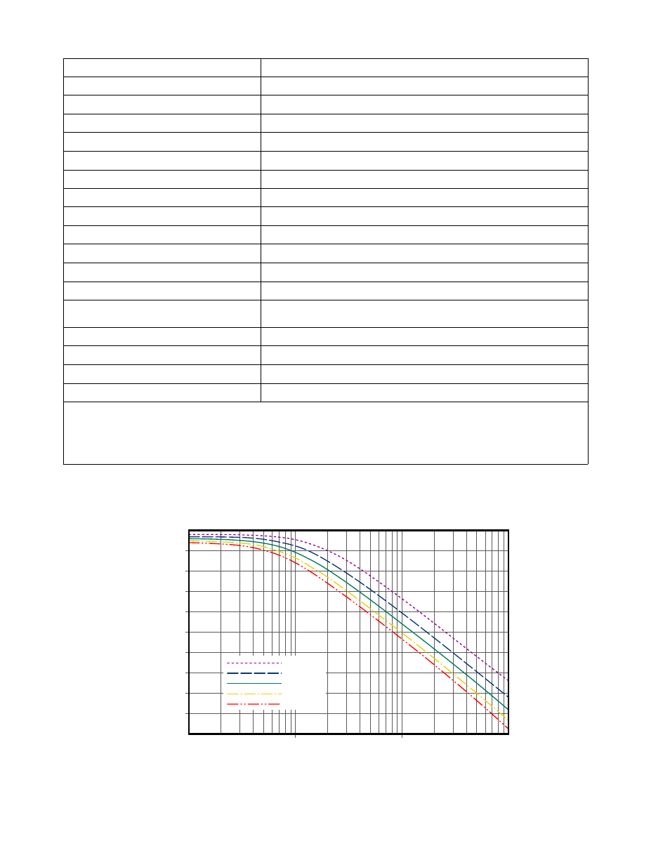
0
-5
Atten
uation (dB)
-10
-15
-20
-25
-30
-35
-40
-45
-50
0.01
0.1
1
Offset from Fo (MHz)
10
73-67-25-Series Systems
10" Diameter 3/4-Wave, Fo = 460 MHz
IL = 1.0 dB
IL = 1.5 dB
IL = 2.0 dB
IL = 2.5 dB
IL = 3.0 dB
Figure 3: Typical transmitter noise suppression using 10” cavities.