Bird Technologies 73-67-25 Series User Manual
Page 29
TX RX Systems Inc. Manual 7-9120-5 07/26/10 Page 23
5) Inject a test signal (-10 dBm) from the tracking
generator into the output port of the isolator.
The test signal should sweep across the operat-
ing bandwidth of the isolator.
6) Compare your displayed waveform against the
example shown in Figure A3 as well as the
specification listed in table A1.
Measuring Insertion Loss (S21)
The insertion loss of your isolator can be verified
by performing the following procedure in a step-by-
step fashion.
1) Make sure the transmitter associated with the
isolator is turned off.
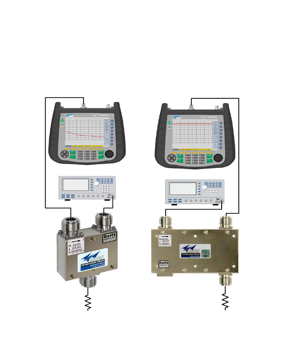
Tracking Generator
Spectrum Analyzer
Bird SignalHawk
50
Ω Load
Figure A1: Verifying Reverse Isolation.
Tracking Generator
Spectrum Analyzer
Bird SignalHawk
50
Ω Load
Figure A2: Verifying Insertion Loss.