Installation overview, Rf cables and connectors, Intermodulation considerations – Bird Technologies 73-67-25 Series User Manual
Page 11
TX RX Systems Inc. Manual 7-9120-5 07/26/10 Page 5
The transmit combiner is a very rugged device and
is well packed for damage-free shipping to any
place in the world. However, a high impact during
shipping can have a detrimental affect. A damaged
shipping container is a sure sign of rough handling.
The most easily damaged parts of the combiner
are the tuning rods. These rods are marked where
they exit from the locking nut with a dab of red var-
nish or other color/type of paint. If this seal appears
to be broken it may indicate that the system has
been detuned in transit.
INSTALLATION OVERVIEW
The combiner should be located in a dry and level
area, indoors. It is best if all transmitters are as
equal in distance as possible from the combiner so
that cable losses are the same for all channels.
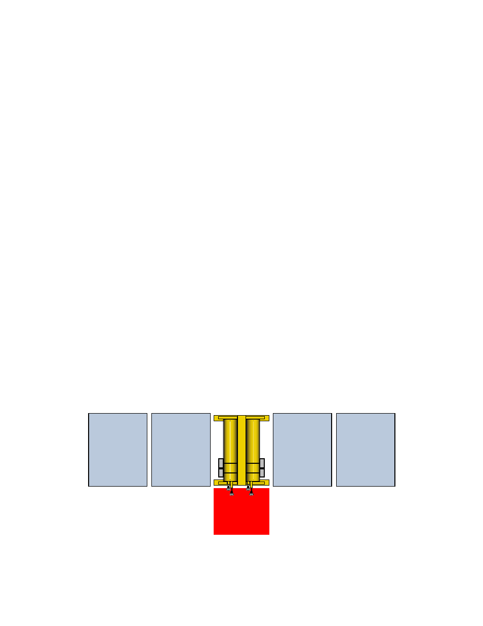
Figure 6 shows a suggested orientation for the
equipment. Two points are important. First, a work
area space should be left as illustrated so that the
tuning controls are easy to access. This will facili-
t a t e t u n i n g w h e n c h a n n e l f r e q u e n c i e s a r e
changed. Secondly, space is needed when adding
expansion channels. If there is a lack of space to
access the side of the combiner, then plan to allow
the rack to be moved into the indicated work area
to facilitate adding channels. This will require some
slack in the cables that connect to the station trans-
mitters. Each transmitter connects to its respective
channel through an ‘N style’ female connector on
the isolator. We recommend using a high quality
double shielded or semi flexible cable.
This system is designed for use with separate
transmit and receive antennas. For best operation,
the transmit and receive antennas should be sepa-
rated vertically by 20 feet with little or no horizontal
offset between antennas. Lesser separations can
be used but with an increased risk of harmful inter-
ference between radio systems. In most cases, it
will be desirable to mount the receive antenna
higher than the transmit antenna to maximize the
talk-back range of low power portable radios.
RF Cables and Connectors
All connections to and from the combiner system
should be made with double-shielded or semi-rigid
heliax cable. High quality 'N' connectors that use
either silver or gold plated contacts should be
used.
Intermodulation Considerations
Following the previously mentioned antenna spac-
ing recommendations will go a long way toward
minimizing or eliminating intermodulation (IM)
interference. IM is the result of a frequency mixing
process that occurs when two or more RF signals
are present simultaneously in the same circuitry
where nonlinearities occur. Product frequencies
generated have frequencies that are determined by
relatively simple mathematical relationships such
as F(im) = 2F1-F2 and are normally determined by
doing a computer intermodulation analysis for the
antenna site. These products can be generated in
a corroded tower joint, metal-roofing, transmitter
final amplifier or the receiver front-end.
Radio
Cabinet
Radio
Cabinet
Radio
Cabinet
Radio
Cabinet
Work
Area
T-Pass
Transmitter
Combiner
Figure 6: Typical combiner installation.