Cavity tuning tip, Coarse cavity tuning – Bird Technologies 73-67-25 Series User Manual
Page 15
TX RX Systems Inc. Manual 7-9120-5 07/26/10 Page 9
4) Tighten the fine tuning locking mechanism.
CAVITY TUNING TIP
When tuning a cavity that has been in service for
some time it is not unusual to find the main tuning
rod hard to move in or out. This occurs because TX
RX uses techniques borrowed from microwave
technology to provide large area contact surfaces
on our tuning plungers. These silver plated sur-
faces actually form a pressure weld that maintains
excellent conductivity. This pressure weld devel-
ops over time and must be broken to move the
main tuning rod. This is easily accomplished by
gently tapping the tuning rod with a plastic screw-
driver handle or small hammer so that it moves into
the cavity. The weld will be broken with no damage
to the cavity.
When adjusting the coarse tuning rod, it is easy to
put the cavity far off resonance and cause most of
the transmitter power to be reflected back into the
isolator output section load. This load should be
capable of dissipating this power or damage could
result. If in doubt about the loads capability, follow
the coarse tuning procedure outlined below. It is
based on the use of a tracking generator which
avoids the need to consider power levels.
COARSE CAVITY TUNING
W h e n a T-Pa s s c av i t y f r e q u e n c y h a s t o b e
changed by over 100 KHz, adjustment of the main
tuning rod is required. Large frequency changes
are more easily observed when using a tracking
generator and a return loss bridge to give a swept
display of the return loss curve. The return loss
curve is a very precise indicator of T-Pass cavity
tuning. The test equipment hookup for doing this is
illustrated in Figure 10 and uses the following
equipment or its equivalent;
1) Spectrum Analyzer that covers the frequencies
of interest such as the Bird Technologies “Sig-
nal Hawk ™”.
2) Signal generator capable of producing the fre-
quencies of interest.
3) Eagle Return Loss Bridge (35 dB directivity).
Model RLB150N3A.
4) Double shielded coaxial cable test leads
(RG142 B\U or RG223/U).
5) 50 Ohm load with at least -35 dB return loss
(1.10:1 VSWR).
6) 3-1268 short circuit connector.
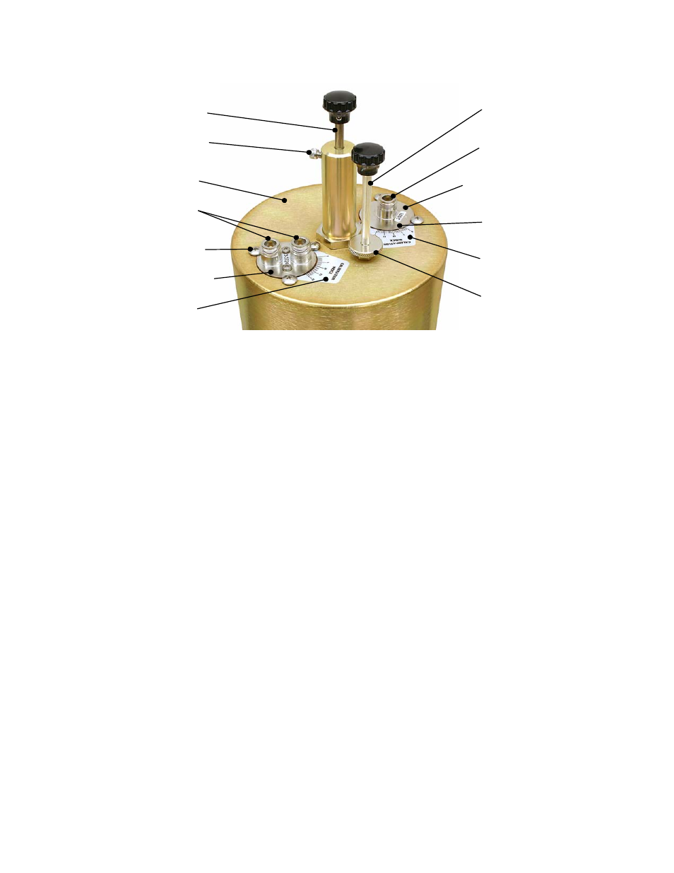
Cavity Resonator
Coarse Tuning Rod
Coarse Tuning Lock
10-32 Cap Screw
Calibration Index
Input/Output Port
Loop Plate Assembly
Loop Plate
Hold Down Screws
Loop Plate Assembly
Input/Output Port
Calibration Mark
Calibration Index
Fine Tuning Rod
Fine Tuning Lock
Knurled Thumb Nut
Figure 9: T-Pass cavity tuning controls details.