Setting cavity insertion loss – Bird Technologies 73-67-25 Series User Manual
Page 20
TX RX Systems Inc. Manual 7-9120-5 07/26/10 Page 14
4) Rotate the cavity body so that the connectors
are oriented the same as those on the other
cavities in the system. Secure the new cavity to
the brackets using (2) stainless band clamps.
5) Tighten the cavity mounting band clamps.
6) Connect the black isolator-to-cavity cable using
a pair of cable pliers to tighten-up the connec-
tors.
7) Connect the new channel to the combiner
using the proper length T-Pass Thruline cable.
Use a pair of cable pliers to tighten these con-
nections.
The required length thruline cable and
new cabling chart has either been fac-
tory supplied or is to be determined
and fabricated by the customer as
determined at the time of order. Use
T-Pass thruline design sheets sup-
plied by the factory.
8) If necessary, reset the cavity insertion loss of
adjacent channels as noted on the Thru-line
cable sheet. Follow the procedure outlined
below under Setting Cavity Insertion Loss.
9) Fine tune the T-Pass cavity of the expansion
channel according to the fine tuning procedure
outlined earlier.
Setting Cavity Insertion Loss
It is sometimes necessary to reset the insertion
loss of a T-Pass cavity filter in order to change its
selectivity. Increasing the loss will increase the
cavity selectivity which may be necessar y to
accommodate more closely spaced channels.
Changing the loss is accomplished by rotating the
coupling loops to change the coefficient of cou-
pling. Both loops are normally adjusted for a given
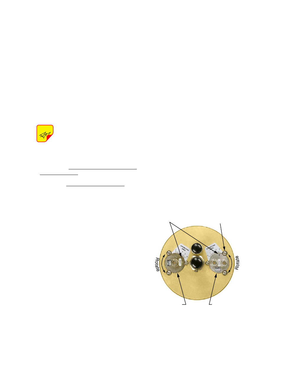
insertion loss setting. Most T-Pass cavities have a
calibration index label beside both loops that gives
a relative indication of their settings, see Figure
13. In actual practice, these marks are not accurate
enough for setting different loss values consis-
tently.
Two procedures are offered for setting the cavity
loss. Both procedures take advantage of the fact
that when a tee connector is placed on a single
bandpass or T-Pass loop, a rejection notch can be
observed across the tee. The depth of the rejection
notch is directly related to the loop's coefficient of
coupling.
The first procedure uses precision rotary attenua-
tors, a signal generator and a RF millivolt meter to
provide very accurate results. The actual loss set-
ting obtained when this procedure is carefully fol-
lowed will be within one tenth of a dB of the desired
value and the return loss will be 20 dB (1.25:1) or
better.
The second procedure uses a spectrum analyzer
and a signal generator and produces slightly less
accurate results. When this procedure is carefully
followed, the loss settings will be within two tenths
of a dB of the desired value and the return loss will
usually be -15 dB (1.5:1 VSWR) or better. The
advantage of this procedure is that it is much faster
to do, does not require precision attenuators and
will yield acceptable results in most cases.
Table 3 is a reference chart for setting T-Pass cav-
ity loss with either procedure. The chart shows the
desired cavity loss settings and the reference set-
ting for both the T-Pass and bandpass loop assem-
bly. The reference notch depth for a given loss is
that which can be observed across a tee connector
connected to either loop assembly.
NOTE
Calibration
Mark
Bandpass
Loop
T-Pass
Loop
Loop Locking
Screws (6 places)
Figure 13: Top view of T-Pass cavity.