Procedure for t-pass loop – Bird Technologies 73-67-25 Series User Manual
Page 22
TX RX Systems Inc. Manual 7-9120-5 07/26/10 Page 16
tor pads. UG-201 BNC to N adapters are used
when connections to N connectors are needed.
PROCEDURE FOR T-PASS LOOP
1) Set the signal generator at the desired fre-
quency (within 1 MHz of operating frequency)
and an output level of approximately -10 dBm.
Set the rotary attenuators for the Reference
Notch Depth Value shown in table 3 for the
desired insertion loss.
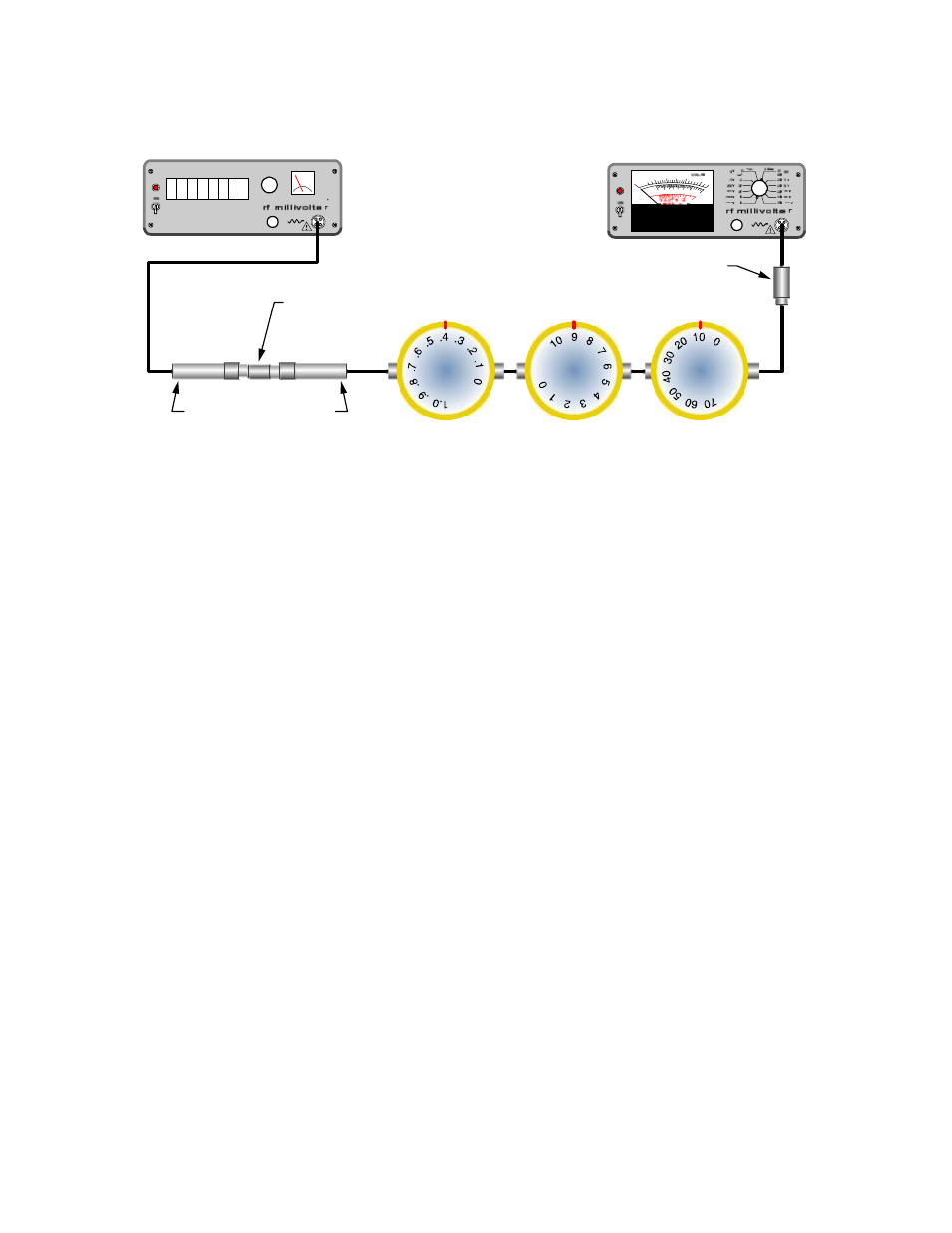
2) Connect the test leads together through the
female union, as shown in Figure 14, and
adjust the range switch and the zero set on the
voltmeter for a convenient reference level (
A
level of 2 on the 0 to 3 scale for example) on the
meter. The generator output level may also be
adjusted slightly if necessary.
3) Remove the bandpass loop from the cavity and
reinsert it, connector end first, back into the cav-
ity and tighten all 3 screws securely. See Fig-
ure 15.
4) Set all three attenuators for 0 dB but leave them
in the circuit.
5) Connect a UG-28A/U Tee connector and UG-
57B/U coupling to the T-Pass loop as shown in
figure 15. Then connect the test leads as
shown. Make sure to install the 3-1268 short cir-
cuit connector from the top of the T-Pass rack.
6) Loosen the main tuning rod locking screw and
slowly slide the tuning rod in or out to obtain a
dip (minimum voltage) in the meter reading
which indicates cavity resonance. Use the fine
tuning control to maximize the dip (the fine tun-
ing rod should not be full in or out which would
indicate that slight adjustment of the main tun-
ing rod is necessary). Note the meter reading.
7) If the meter reading is greater or less than the
reference level from step 2, the T-Pass loop
rotation will have to be adjusted. If the meter
reading is greater than the reference level, the
loop will have to be rotated so that the calibra-
tion mark on the loop points to a slightly higher
number on the calibration index label. Con-
versely, if the meter reading is less than the ref-
erence, the loop will have to be rotated so that
the index mark points to a slightly lower number
on the calibration index. Loosen the three loop
locking screws and rotate the loop so that the
index mark is moved to the next higher or lower
calibration tag number as needed and tighten
the 3 locking screws. Note that tight screws are
necessary for accuracy.
ZERO
SET
ZERO
SET
0 00 00 0 00
1
2
3
3 4 5 6 7 8 9
10
Modulated
Signal Source
RF Voltmeter
Rotary Attenuators
Set to Loop Reference Settings
0.1 dB/Div.
1.0 dB/Div.
10 dB/Div.
All cables are 50 Ohm
coaxial. Double shielded
cables preferred.
UG914/U
Female-Female
Connector
10 dB Attenuator Pads
50 Ohm Adaptor
Figure 14: Setting loop adjustment reference level.