Cavity loss setting procedure 2, Required test equipment, Procedure for t-pass loop – Bird Technologies 73-67-25 Series User Manual
Page 24
TX RX Systems Inc. Manual 7-9120-5 07/26/10 Page 18
the index mark points to a slightly lower number
on the calibration index. Loosen the three loop
locking screws and rotate the loop so that the
index mark is moved to the next higher or lower
calibration tag number as needed and tighten
the 3 locking screws. Note that tight screws are
necessary for accuracy.
7) Repeat steps 5 and 6 until the minimum meter
reading is equal to the reference level from step
2. Rotation of loops will change the cavity fre-
quency slightly.
8) Make sure that all the loop locking screws are
tight. The cavity loops are now set and the cav-
ity should now be tuned to the desired fre-
quency.
Cavity Loss Setting Procedure 2
This procedure uses a spectrum analyzer and sig-
nal generator.
REQUIRED TEST EQUIPMENT
1) Spectrum Analyzer and a signal generator.
2) Two 10 dB fixed attenuator pads with BNC
connectors. JFW Industries model 50F-010.
3) UG-914/U, BNC(F) to BNC(F) union.
TX RX Systems' part # 8-5805.
4) UG-28A/U, N(F), N(F), N(F) tee.
5) UG-57B/U, N(M)-N(M) coupling.
6) Two, UG-201A/U BNC(F)-N(M) adapter.
TX RX Systems' part # 8-5814.
7) 50 ohm coaxial cable test leads with BNC male
connectors (high quality cable).
We have found it convenient to use test cables with
BNC connectors. They allow for a more convenient
connection to test equipment and small attenuator
pads. UG-201 BNC to N adapters are used when
connections to N connectors are needed.
PROCEDURE FOR T-PASS LOOP
1) Remove the screws that hold in the bandpass
loop assembly; remove the assembly; invert it
and place it back into the cavity (see Figure
17). The coupling loop will be visible. Install and
tighten the three locking screws.
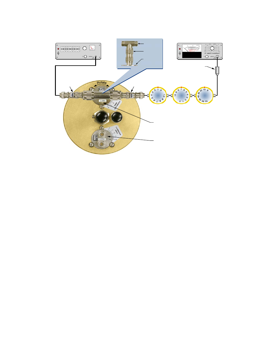
Modulated
Signal Source
RF Voltmeter
Rotary Attenuators
Set to Loop Reference Settings
0.1 dB/Div.
1.0 dB/Div.
10 dB/Div.
50 Ohm Adaptor
UG-28A/U
UG-57B/U
Bandpass
Loop
10 dB Pad
10 dB Pad
Previously calibrated T-Pass Loop 3-1268
short circuit removed.
Small Circle on Bandpass Loop indicates
ground end of loop and should be
oriented as shown.
Figure 16: Setting the bandpass loop using step attenuators.