Relay rack procedure, 10” cavities) – Bird Technologies 73-67-25 Series User Manual
Page 18
TX RX Systems Inc. Manual 7-9120-5 07/26/10 Page 12
cable sheet. Follow the procedure outlined
below under Setting Cavity Insertion Loss.
11) Fine tune the T-Pass cavity of the expansion
channel according to the fine tuning procedure
outlined earlier.
RELAY RACK PROCEDURE
(10” CAVITIES)
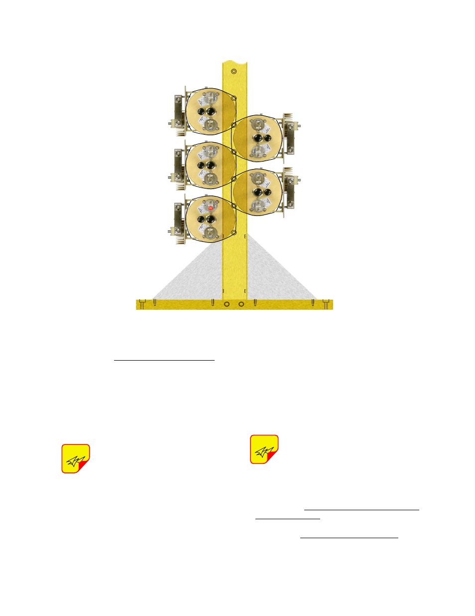
Because of their width, 10” cavities
are mounted in relay racks with a ver-
tical orientation as shown in Figure
12.
1) Install the expansion cavities to the rack above
existing channels using four mounting screws.
Make sure you leave sufficient space between
the upper and lower cavity groups so that the
tuning rods and interconnect cables do not
interfere.
2) Connect the black isolator-to-cavity cable using
a pair of cable pliers to tighten-up the connec-
tors.
3) Connect the new channel to the combiner
using the proper length T-Pass Thruline cable.
Use a pair of cable pliers to tighten these con-
nections.
The required length thruline cable and
new cabling chart has either been fac-
tory supplied or is to be determined
and fabricated by the customer as
determined at the time of order. Use
T-Pass thruline design sheets sup-
plied by the factory.
4) If necessary, reset the cavity insertion loss of
adjacent channels as noted on the Thru-line
cable sheet. Follow the procedure outlined
below under Setting Cavity Insertion Loss.
NOTE
NOTE
Figure 11: Peg-rack mounting details.