Procedure for bandpass loop – Bird Technologies 73-67-25 Series User Manual
Page 26
TX RX Systems Inc. Manual 7-9120-5 07/26/10 Page 20
slightly less than the reference. The Notch
depth will tend to increase slightly as all three
locking screws are tightened.
12) Remove the bandpass loop and place it back
into the cavity with the connector-end up.
PROCEDURE FOR BANDPASS LOOP
1) The Bandpass loop should be installed with the
connector up and the ground point circle ori-
ented toward the center of the cavity as shown
in Figure 18.
2) Connect the test leads, with 10 dB pads
attached, to the spectrum analyzer; turn it on
and let it warm up for at least 30 minutes if this
has not been done.
3) Note the Reference Notch Depth value for the
Bandpass loop assembly to be adjusted from
table 3.
4) Set The spectrum analyzer for the frequency of
the channel of interest (within 5 MHz of actual
operating frequency).
5) If the Reference Notch Depth is 8 dB or less
then set the display for a vertical range of 2dB/
div otherwise set it for 10dB/div.
6) Temporarily connect the test leads from the
spectrum analyzer together through a UG-914
BNC union to set the zero reference. Make sure
to use the 10 dB pads which should remain on
the test cables for all measurements.
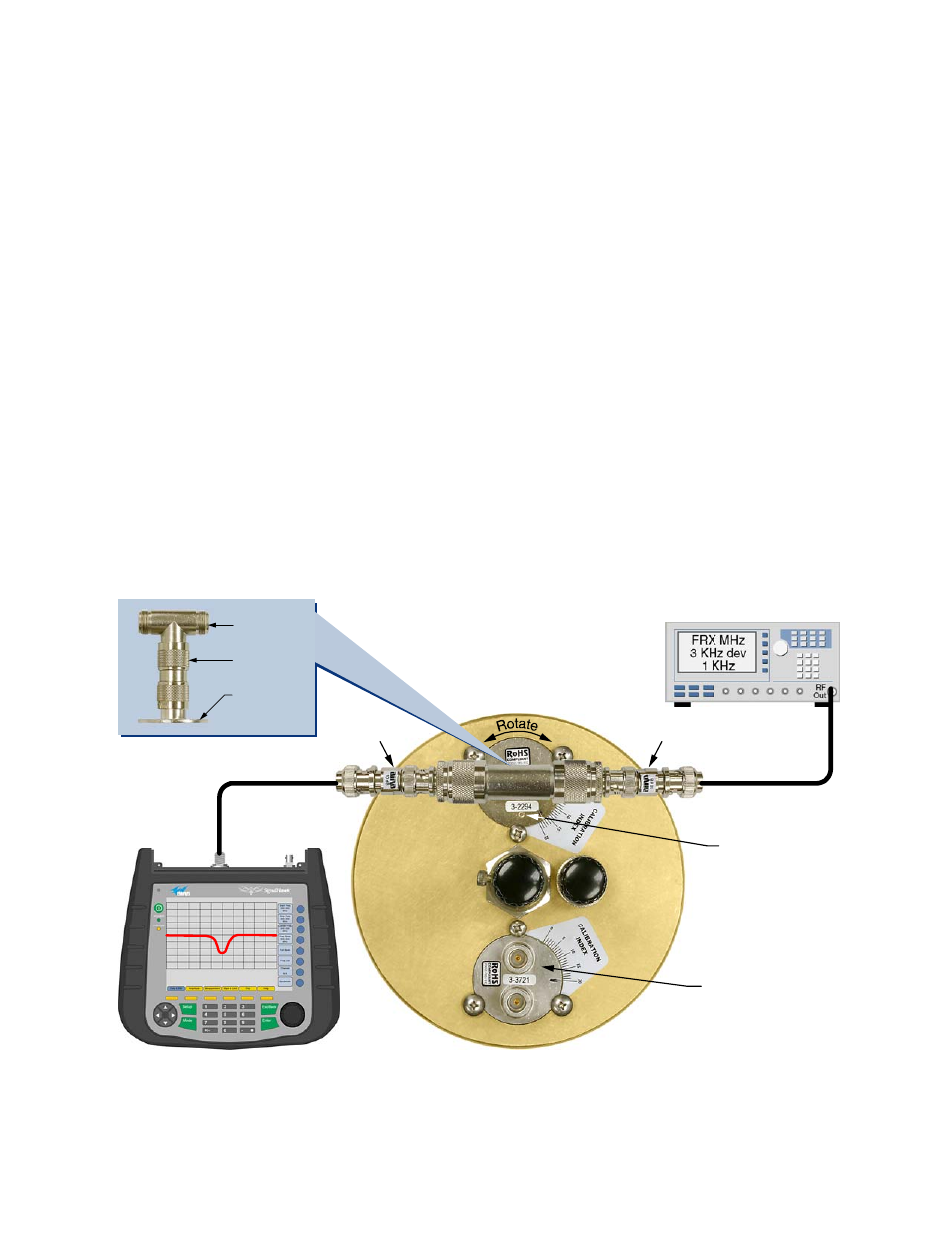
7) Connect a UG-28 tee and a UG-57 coupling to
the bandpass loop as shown in figure 18.
8) Connect the test leads from the spectrum ana-
lyzer to the tee connector as shown in figure 18.
9) Adjust the cavities main tuning rod so that a
rejection notch appears in the center of the dis-
play.
10) Loosen the three loop locking screws and
rotate the loop assembly to obtain the refer-
ence notch depth from step 3. Note that the
tightness of the locking screws affects the
depth of the rejection notch slightly, it is usually
10 dB Pad
10 dB Pad
UG-28A/U
UG-57B/U
Bandpass
Loop
Previously calibrated
T-Pass Loop 3-1268
short circuit removed.
Small Circle on
Bandpass Loop
indicates ground
end of loop and
should be oriented
as shown.
Spectrum Analyzer
Bird SignalHawk
Signal Generator
Figure 18: Setting a bandpass loop for specific cavity insertion loss.