General description – Bird Technologies 73-67-25 Series User Manual
Page 7
TX RX Systems Inc. Manual 7-9120-5 07/26/10 Page 1
GENERAL DESCRIPTION
The model 73-67-11/25-XX-NN Series T-Pass
Transmit Combiners are designed to connect multi-
ple transmitters to a common antenna. They use
three-port bandpass filters (called T-Pass cavities)
and ferrite isolators to provide low channel inser-
tion loss, high isolation between transmitters, high
antenna-to-transmitter isolation, high intermodula-
tion suppression, and excellent transmitter noise
suppression. T-Pass transmit combiners are
broadband and easily adaptable to the most diffi-
cult duplex system design requirements.
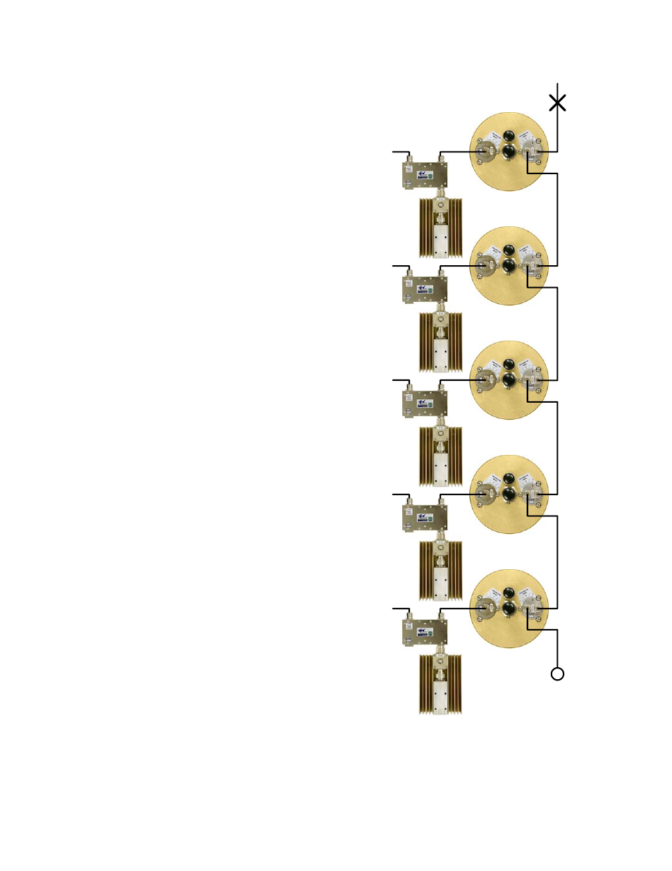
The block diagram of a typical transmit combiner is
shown in Figure 1. The T-Pass filter passes one
narrow band of frequencies and attenuates all oth-
ers with increasing attenuation above and below
the pass frequency. The T-Pass filter has a “dual-
port” output loop plate which allows the filter to be
easily connected to other T-Pass filters. Connec-
tions between the filters are made with a “thru-line”
cable that behaves like a low loss 50 Ohm trans-
mission line. The thru-line cables are individually
optimized to their own channel frequency. No com-
promises are necessary to accommodate other
channel frequencies. Each channel can therefore
be anywhere in a very broad frequency range.
An isolator is added at the input to each T-pass
channel to increase channel isolation. The ferrite
isolators will isolate the transmitter from unwanted
signals that enter the system via the antenna. The
transmitter sees an excellent impedance match on
its output, because the isolator absorbs reflected
power that would otherwise enter the transmitters
output stage. This improves the stability, spectral
purity and long-term reliability of the transmitter.
The model 73-67-11/25-XX-NN Series T-Pass
transmit combiners are available with either 6.625”
or 10” cavities. TX combiners constructed with
6.625” cavities are ideal for operation at channel
separations of 115 KHz or more, with 110 to 150
Watt transmitters. These models are suitable for
19” relay rack mounting or TX RX peg rack mount-
ing. TX combiners constructed with high perfor-
mance 10” diameter cavities, which have higher
selectivity and power handling capabilities, allow
operation at 75 KHz minimum separation with 125
to 150 Watt transmitters. In addition, High power
10” diameter models are also available which con-
tain 250 Watt dual isolators with 100 or 250 Watt
loads.
S
TX5
TX4
TX3
TX2
TX1
Transmitter Combiner (T-Pass)
Figure 1: Block diagram of a typical TX T-Pass
combiner. Typical five channel system shown as
an example.