General installation procedure – Bird Technologies 73-67-25 Series User Manual
Page 12
TX RX Systems Inc. Manual 7-9120-5 07/26/10 Page 6
Both cavity filters and ferrite isolators isolate the
transmitters connected to the combiner from one-
another thus reducing intermodulation interference.
However in all transmitter combiners, intermodula-
tion products are reduced in strength but never
completely eliminated. They have to be reduced by
an amount to meet the federal Communications
Commission,
43 + 10 Log(Power Out) rule for spu-
rious output reduction. Because of the limitations
imposed by the tension and friction joints in con-
nectors, IM products will be down 100 to 120 dB
below carrier so they are still strong enough to
cause problems if they fall on a near-by receiver
frequency.
To avoid transmitter generated IM problems, do
not put two channels on the same combiner that
your IM software predicts will cause interference by
generating either 3rd or 5th order IM products.
Having at least two transmitter combiners allows
maximum flexibility in dealing with transmitter gen-
erated IM.
General Installation Procedure
1) Install the peg rack or relay rack in the radio
equipment room.
2) Connect the transmitters and the transmitting
antenna to the appropriate connectors on the
cavities.
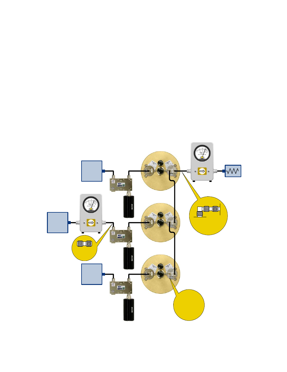
UG27 Elbow Connector
& UG57 Male-Male
Adaptor
UG57
Male-Male
Transmitter
Transmitter
Transmitter
Single
or Dual
Section
Isolators
Single
or Dual
Section
Isolators
Single
or Dual
Section
Isolators
T-Pass
Cavity Filter
Channel 3
Channel 2
Channel 1
Wattmeter 2
50 Ohm
Load
Wattmeter 1
This T-Pass Loop
requires a 3-1268
short circuit
connector
Figure 7: Equipment hookup for measuring T-Pass channel performance.