Cavity loss setting procedure 1, Required test equipment – Bird Technologies 73-67-25 Series User Manual
Page 21
TX RX Systems Inc. Manual 7-9120-5 07/26/10 Page 15
Cavity Loss Setting Procedure 1
This procedure uses precision rotary attenuators, a
signal generator and an RF millivolt meter.
REQUIRED TEST EQUIPMENT
1) Signal generator capable of producing a CW
signal level of at least -10 dBm with variable
output level capability at the frequency of inter-
est.
2) An RF voltmeter with a 0.001 V (-50 dBm)
scale and a 50 ohm input adapter. Helper
Instruments RF millivolter used for this exam-
ple.
3) Rotary Attenuators, 1@ 0-1 dB in 0.1 dB incre-
ments. 1@ 0-10 dB in 1.0 dB increments. 1@
0-70 dB in 10 dB increments. JFW Industries
model 50BR-017.
4) Two 10 dB fixed attenuator pads with BNC
connectors. JFW Industries model 50F-010.
5) UG-914/U, BNC(F) to BNC(F) union.
TX RX Systems' part # 8-5805.
6) UG-28A/U, N(F), N(F), N(F) tee.
7) UG-57B/U, N(M)-N(M) coupling.
8) Two, UG-201A/U BNC(F)-N(M) adapter.
TX RX Systems' part # 8-5814.
9) 50 ohm coaxial cable test leads with BNC male
connectors (high quality cable).
A spectrum analyzer may be used in place of the
RF voltmeter. However, the personnel doing the
work should fully understand the procedure and
understand the use of the analyzer for this applica-
tion.
We have found it convenient to use test cables with
BNC connectors. They allow for more convenient
connection to test equipment and to small attenua-
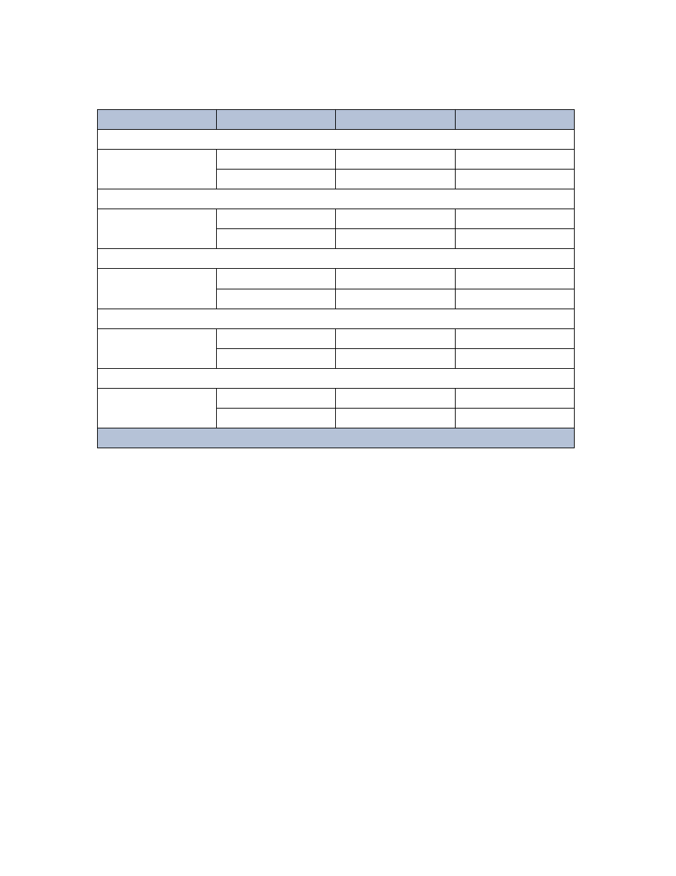
Cavity Loss (dB)
Coupling Loop Type
TXRX Part #
Reference Notch Depth
1.0
T-Pass
3-3724
-9.2
Bandpass
2-0675
-12
1.5
T-Pass
3-3724
-7.4
Bandpass
2-0675
-10.2
2.0
T-Pass
3-3724
-5.6
Bandpass
2-0675
-8.8
2.5
T-Pass
3-3724
-4.4
Bandpass
2-0675
-8.0
3.0
T-Pass
3-3724
-3.6
Bandpass
2-0675
-7.2
Table 3: Cavity insertion loss reference loop settings.