Tuning specifics, Fine cavity tuning – Bird Technologies 73-67-25 Series User Manual
Page 14
TX RX Systems Inc. Manual 7-9120-5 07/26/10 Page 8
ing action of filters. Since the filters are usually
tuned using laboratory grade 50 ohm loads, the
tuning adjustment that produces this improved
match will be slightly different than the factory
adjustment. While this tuning may produce slightly
greater power output readings, it will rarely pro-
duce any discernible change in system perfor-
mance and may detune any notching circuitry
contained in the cavities.
It is our recommendation that channel tuning only
be attempted under the previously mentioned con-
ditions or when it is suspected that the combiner
has been tampered with or subjected to extreme
shock in shipping or installation. This condition is
indicated when the channel loss is in excess of that
expected from actual measurement of power input
and output.
Tuning Specifics
Tuning of the combiner consists of tuning the indi-
vidual T-Pass channels. T-Pass channel tuning
involves cavity filter tuning. The isolators are
broad band and do not require adjustments.
The procedures for tuning cavities follows.
FINE CAVITY TUNING
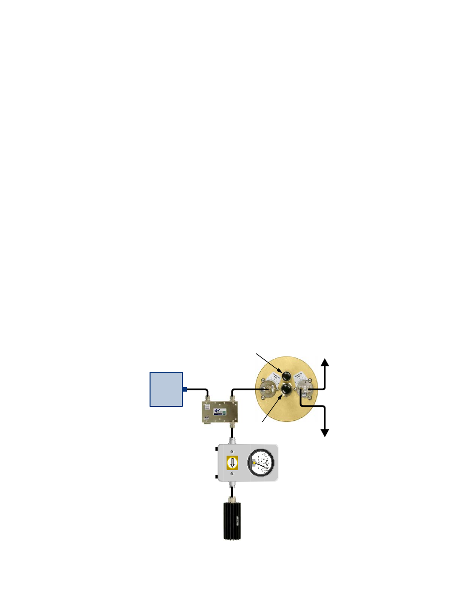
Figure 8 shows hookups which are suitable for fine
tuning any channel under power while installed in
the combiner. The term fine tuning here refers to
cavities that have already been tuned to frequency
and may only require adjustment of the fine tuning
control (+/- 50 KHz). The transmitter is used as a
signal source and the cavity is adjusted for mini-
mum reflected power.
Procedure
With the transmitter keyed, the cavity fine tuning
control is adjusted (pushed in or out) to obtain a
minimum meter reading. See Figure 9 for a detail
of the cavity tuning controls. If a minimum meter
reading is obtained with the fine tuning rod fully in
or completely out, do the following:
1) Set the fine tuning rod so that about 1/2 of its
length is inserted into the cavity.
2) Loosen the coarse tuning rod locking screw (5/
32”/4mm Allen/Hex-key wrench required) and
move the rod in or out slightly to obtain mini-
mum meter reading. Small movements of the
coarse tuning rod are facilitated by tapping the
rod with the handle end of a screw driver while
gently pushing or pulling the main tuning rod.
Tighten the coarse tuning locking screw.
3) Adjust the fine tuning control for a minimum
meter reading.
Transmitter
Output
Section
Termination
Two Single Section
or One Dual Isolators
T-Pass
Cavity Filter
Wattmeter
To Other
Channels
To Other
Channels
Input
50 Ohm
Termination
Fine
Tuning
Output
Coarse
Tuning
Figure 8: Using a wattmeter for T-Pass cavity fine tuning.