Bird Technologies 73-67-25 Series User Manual
Page 25
TX RX Systems Inc. Manual 7-9120-5 07/26/10 Page 19
2) Connect the test leads to the spectrum ana-
lyzer; turn it on and let it warm up for at least 30
minutes.
3) Connect the 10 dB attenuator pads to the test
leads. They will remain connected for all subse-
quent measurements.
4) Note the Reference Notch Depth value for the
T-Pass loop assembly to be adjusted from table
3.
5) Set the spectrum analyzer for the frequency of
the channel of interest (within 1 MHz of actual
operating frequency).
6) If the Reference Notch Depth is 8 dB or less
then set the display for a vertical range of 2dB/
div otherwise set it for 10dB/div.
7) Temporarily connect the test leads from the
spectrum analyzer together through a UG-914
BNC union to set the zero reference.
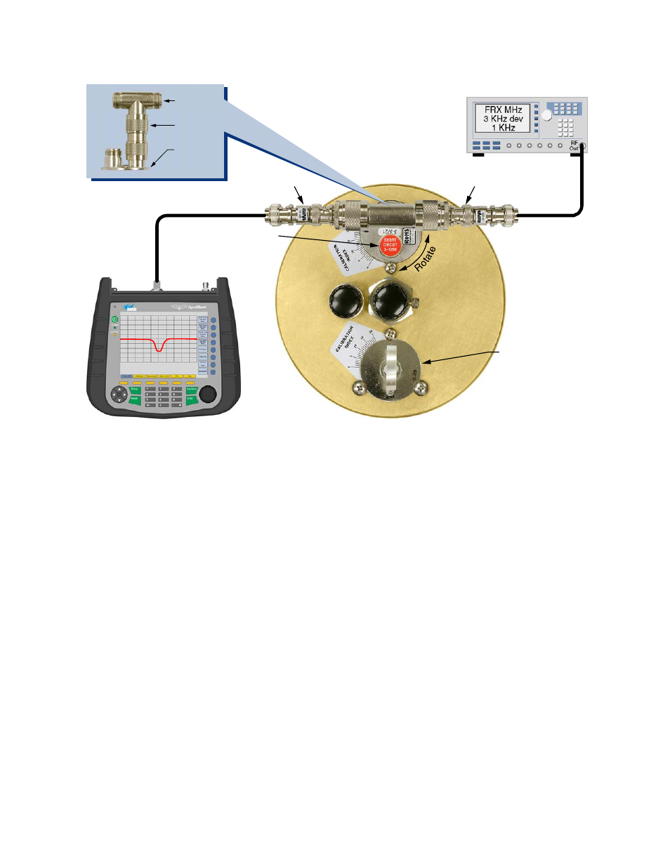
8) Connect a UG-28 tee and a UG-57 coupling to
the T-Pass loop as shown in figure 17.
9) Connect the test leads from the spectrum ana-
lyzer to the tee connector as shown in figure 17.
10) Adjust the cavities main tuning rod so that a
rejection notch appears in the center of the dis-
play.
11) Loosen the three loop locking screws and
rotate the loop to obtain the reference notch
depth from step 4. Tighten the T-Pass loop
locking screws only. Note that the tightness of
the locking screws affects the depth of the
rejection notch slightly. It is usually necessary
to rotate the loop for a notch depth that is
UG-28A/U
UG-57B/U
T-Pass
Loop
10 dB Pad
10 dB Pad
Short Circuit
Connector 3-1268
from top of rack
Bandpass Loop
turned upside down
with connector
inserted into cavity.
Loop visible and
screws tight.
Spectrum Analyzer
Bird SignalHawk
Signal Generator
Figure 17: Setting a T-Pass loop for specific cavity insertion loss.