Procedure for bandpass loop – Bird Technologies 73-67-25 Series User Manual
Page 23
TX RX Systems Inc. Manual 7-9120-5 07/26/10 Page 17
8) Repeat steps 6 and 7 until the minimum meter
reading is equal to the reference level from step
2. Rotation of loops will change the cavity fre-
quency slightly.
9) The Bandpass loop should be reinstalled with
the connector facing upward and the ground
point circle oriented toward the center of the
cavity as shown in Figure 16.
10) Remove the short circuit connector from the T-
Pass loop.
PROCEDURE FOR BANDPASS LOOP
1) Maintain the previous signal generator settings
and set the rotary attenuators for the proper set-
ting as shown in table 3 for the Bandpass Loop.
2) Connect the test leads together through the
female union and adjust the range switch and
the zero set on the voltmeter for a reference
level (
A level of 2 on the 0 to 3 scale is conve-
nient) on the meter. See figure 14. The genera-
tor output level may also be adjusted slightly if
convenient.
3) Set all three attenuators for 0 dB but leave them
in the circuit.
4) Connect a UG-107 Tee and the UG-57B/U to
the Bandpass loop as shown on figure 16. Then
connect the test leads as shown. Make sure the
short circuit connector has been removed from
the T-Pass loop.
5) Loosen the main tuning rod locking screw and
slowly slide tuning rod in or out to obtain a dip
(minimum voltage) in the meter reading which
indicates cavity resonance. Use the fine tuning
control to maximize the dip (the fine tuning rod
should not be full in or out which would indicate
that slight adjustment of the main tuning is nec-
essary). Note the meter reading.
6) If the meter reading is greater or less than the
reference level from step 2, the bandpass loop
rotation will have to be adjusted. If the meter
reading is greater than the reference level, the
loop will have to be rotated so that the calibra-
tion mark on the loop, points to a slightly higher
number on the calibration index label. Con-
versely, if the meter reading is less than the ref
erence, the loop will have to be rotated so that
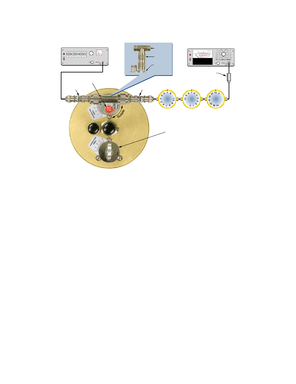
Modulated
Signal Source
RF Voltmeter
Rotary Attenuators
Set to Loop Reference Settings
0.1 dB/Div.
1.0 dB/Div.
10 dB/Div.
50 Ohm Adaptor
UG-28A/U
UG-57B/U
T-Pass
Loop
10 dB Pad
10 dB Pad
Short Circuit Connector
3-1268 from top of rack
Bandpass Loop turned upside down
with connector inserted into cavity.
Loop visible and screws tight.
Figure 15: Setting the T-Pass loop using step attenuators.