Bird Technologies 73-67-25 Series User Manual
Page 30
TX RX Systems Inc. Manual 7-9120-5 07/26/10 Page 24
2) Disconnect the input and output cable to the
isolator.
3) Connect a tracking generator and spectrum
analyzer to the input and output ports of the iso-
lator respectively, as shown in Figure A2.
4) Make sure that a 50 Ohm load is connected to
the load port of the isolator. If you are testing
the isolator on the bench make sure you con-
nect a load. If you are testing the isolator while it
is still mounted on the system rack/cabinet
leave the existing load connected.
5) Inject a test signal into the input of the isolator
from the tracking generator which will sweep
across the operating bandwidth of the isolator.
The strength of the test signal should be -10
dBm.
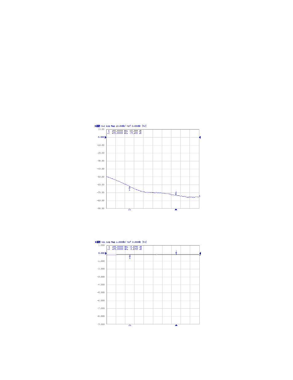
6) Compare your displayed waveform against the
example shown in Figure A4 and the specifica-
tion listed in table A1.
Figure A4: Typical insertion loss waveform.
Figure A3: Typical reverse isolation waveform.