Module indicators – Rockwell Automation 1440-VST02-01RA XM-120 Eccentricity Module User Manual
Page 45
Publication GMSI10-UM010C-EN-P - May 2010
Installing the XM-120 Eccentricity Module 37
Module Indicators
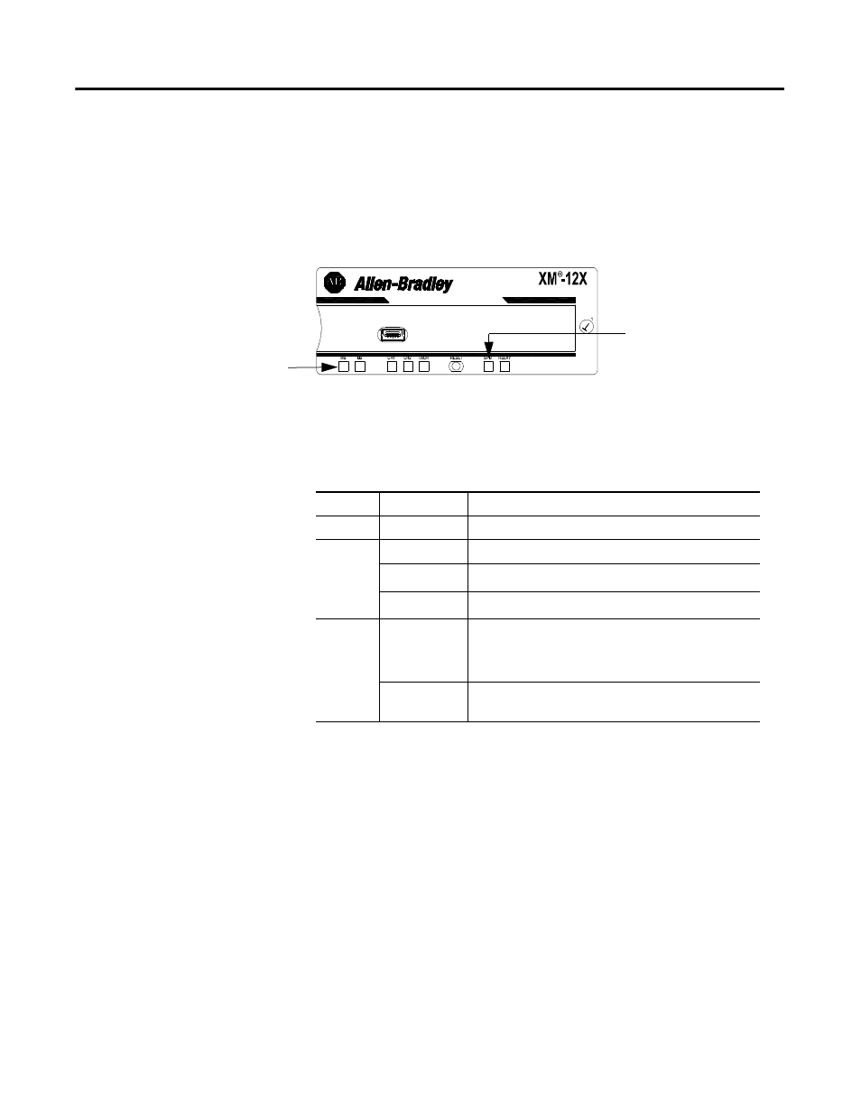
The Eccentricity module has seven LED indicators, which include a module
status (MS) indicator, a network status (NS) indicator, a status indicator for
each channel (CH1, CH2, and TACH), an activation indicator for Eccentricity,
and a status indicator for the Relay. The LED indicators are located on top of
the module.
Figure 2.23 LED Indicators
The following tables describe the states of the LED status indicators.
Module Status (MS) Indicator
1
Program Mode - Typically this occurs when the module configuration settings are being updated with the XM
Serial Configuration Utility. In Program Mode, the module does not perform its normal functions. The signal
processing/measurement process is stopped, and the status of the alarms is set to the disarm state to prevent
a false alert or danger status.
2
Run Mode - In Run Mode, the module collects measurement data and monitors each vibration measurement
device.
Module Indicators
Eccentricity LED
Color
State
Description
No color
Off
No power applied to the module.
Green
Flashing Red
Module performing power-up self test.
Flashing
Module operating in Program Mode
1
.
Solid
Module operating in Run Mode
2
.
Red
Flashing
•
Application firmware is invalid or not loaded.
Download firmware to the module.
•
Firmware download is currently in progress.
Solid
An unrecoverable fault has occurred. The module may
need to be repaired or replaced.