Rockwell Automation 1440-VST02-01RA XM-120 Eccentricity Module User Manual
Page 41
Publication GMSI10-UM010C-EN-P - May 2010
Installing the XM-120 Eccentricity Module 33
The DB-9 connector should be wired to the terminal block as shown.
•
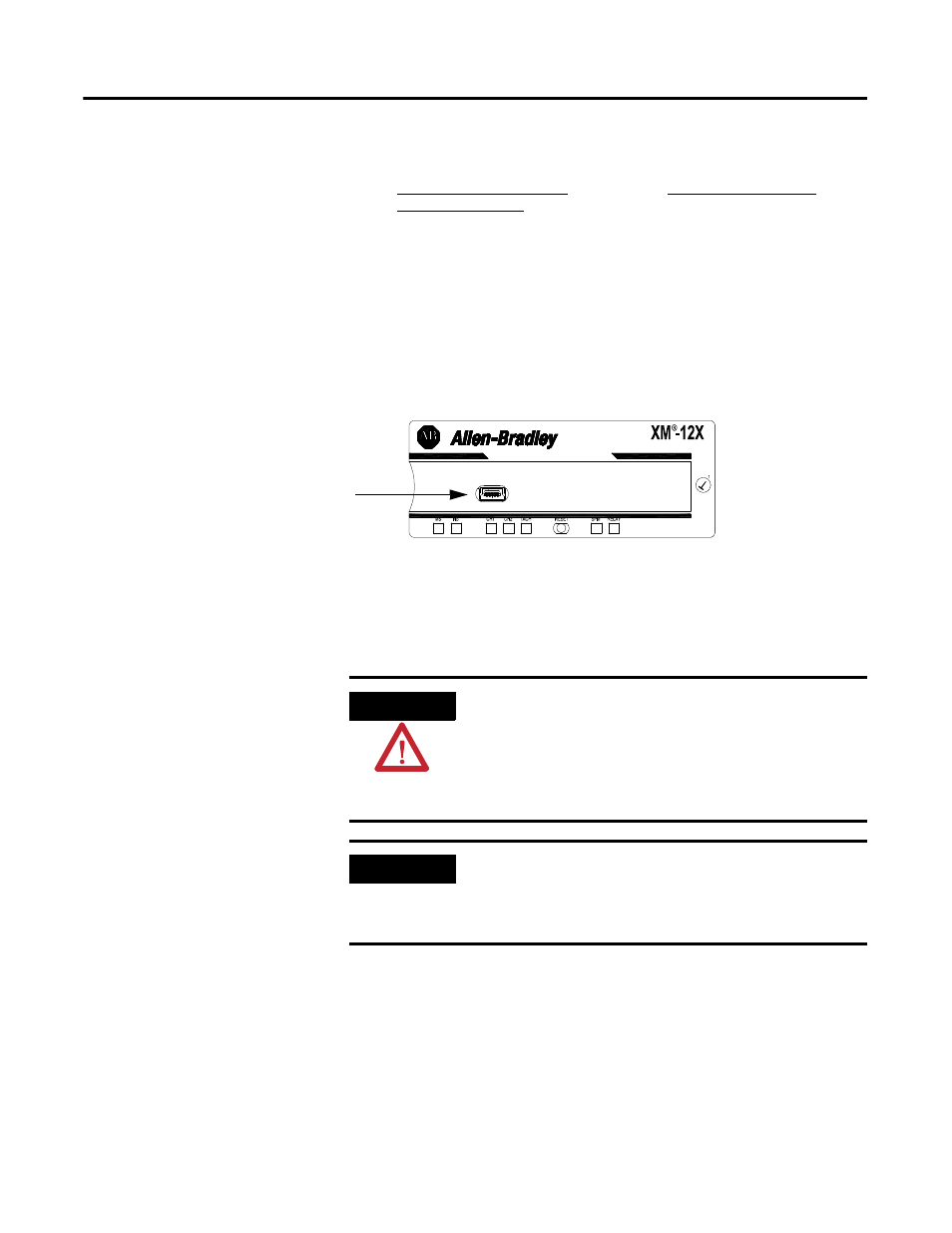
Mini Connector - The mini connector is located on the top of the
module, as shown below.
Figure 2.22 Mini Connector
A special cable (Cat. No. 1440-SCDB9FXM2) is required for this
connection. The connector that inserts into the PC is a DB-9 female
connector, and the connector that inserts into the module is a USB
Mini-B male connector.
XM-120 Terminal Base Unit
(Cat. No. 1440-TB-A)
DB-9 Female Connector
TX Terminal (terminal 7) ----------------------
Pin 2 (RD - receive data)
RX Terminal (terminal 8) ----------------------
Pin 3 (TD - transmit data)
RTN Terminal (terminal 9) ---------------------
Pin 5 (SG - signal ground)
mini connector
WARNING
If you connect or disconnect the serial cable with power
applied to the module or the serial device on the other end
of the cable, an electrical arc can occur. This could cause an
explosion in hazardous location installations. Be sure that
power is removed or the area is nonhazardous before
proceeding.
IMPORTANT
If 24 V Common is not referenced to earth ground, we
recommend you use an RS-232 isolator, such as Phoenix
PSM-ME-RS232/RS232-P (Cat. No. 1440-ISO-232-24), to
protect both the XM module and the computer.