Output power wiring – Rockwell Automation 20D PowerFlex 700S/700H Frames 10...14 IP00, NEMA/UL Open Power Structures User Manual
Page 49
Rockwell Automation Publication PFLEX-IN020C-EN-P - July 2013
49
PowerFlex 700S and 700H Frames 10...14 IP00, NEMA/UL Open Power Structures
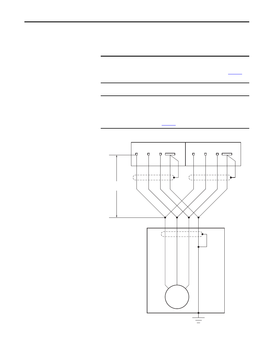
Output Power Wiring
Frame 12 and 14 drives utilize two parallel power structures, and therefore have
two sets of output power terminals. You must connect the motor to both sets of
output power terminals.
Figure 36 - Frame 12 and 14 Output Power Wiring Example
IMPORTANT
Parallel wiring must have the same cable dimensions, type and routing. Non-
symmetrical wiring may cause unequal loading between the converters and
reduce the drive’s ability to deliver current to the motor. Refer to
Figure 36
below for details.
IMPORTANT
The minimum cable length for parallel motor cables from the drive to the point
where the cables connect is 5m (16.4 ft.). Join the parallel cables at the motor
end (not the drive end). Or, install a reactor on the output of each power
module with a minimum of 5 μH prior to joining the parallel cables at the
motor end. Refer to
Figure 36
below for details.
1T1
1T2
1T3
2T1
2T2
2T3
PE
PE
Motor Frame
Motor
5 m (16.4 ft)
minimum