Du/dt filter installation – Rockwell Automation 20D PowerFlex 700S/700H Frames 10...14 IP00, NEMA/UL Open Power Structures User Manual
Page 48
48
Rockwell Automation Publication PFLEX-IN020C-EN-P - July 2013
PowerFlex 700S and 700H Frames 10...14 IP00, NEMA/UL Open Power Structures
du/dt Filter Installation
Frame 14 drives can be ordered with or without du/dt filters. The du/dt filter
limits the rate of change of output voltage and the rate of change in the IGBT or
output transistor switching event.
Refer to the Wiring and Grounding Guidelines for Pulse Width Modulated
(PWM) AC Drives, publication
, for minimum inductance on
installations where du/dt filters are not installed.
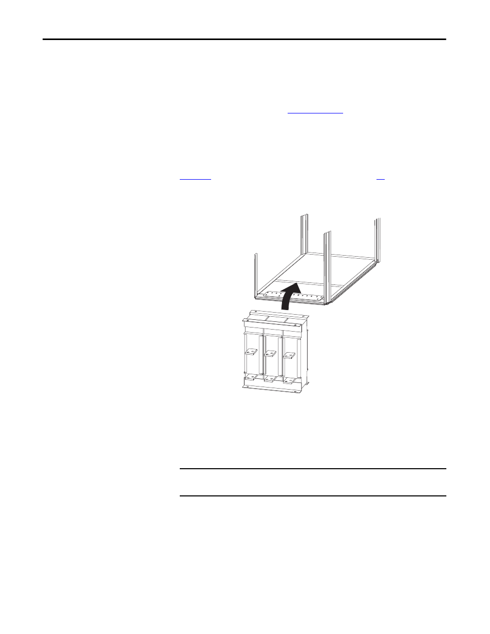
The recommended location for the du/dt filters is at the bottom of the same
enclosure with the inverters, as close to the rear wall as possible.
Secure the du/dt filters on an assembly plate or by using mounting rails. See
Figure 35
below. Refer to Component Dimensions on page
53
for more details.
Figure 35 - Recommended du/dt Filter Mounting Location
When cables are used for power wiring, they must be copper and rated at 90° C
(194° F). For frame 14 drives, power connections between the output power
terminals and the du/dt filters are typically made using busbars, however, copper
cables may be used.
Connect power cables between the appropriate output power terminals (U/T1,
V/T2, W/T3) and the input terminals of the du/dt filters.
IMPORTANT
Busbar alignment should be vertical to allow the maximum flow of cooling air
through the enclosure.