Frame 10…12 component/enclosure configurations – Rockwell Automation 20D PowerFlex 700S/700H Frames 10...14 IP00, NEMA/UL Open Power Structures User Manual
Page 10
10
Rockwell Automation Publication PFLEX-IN020C-EN-P - July 2013
PowerFlex 700S and 700H Frames 10...14 IP00, NEMA/UL Open Power Structures
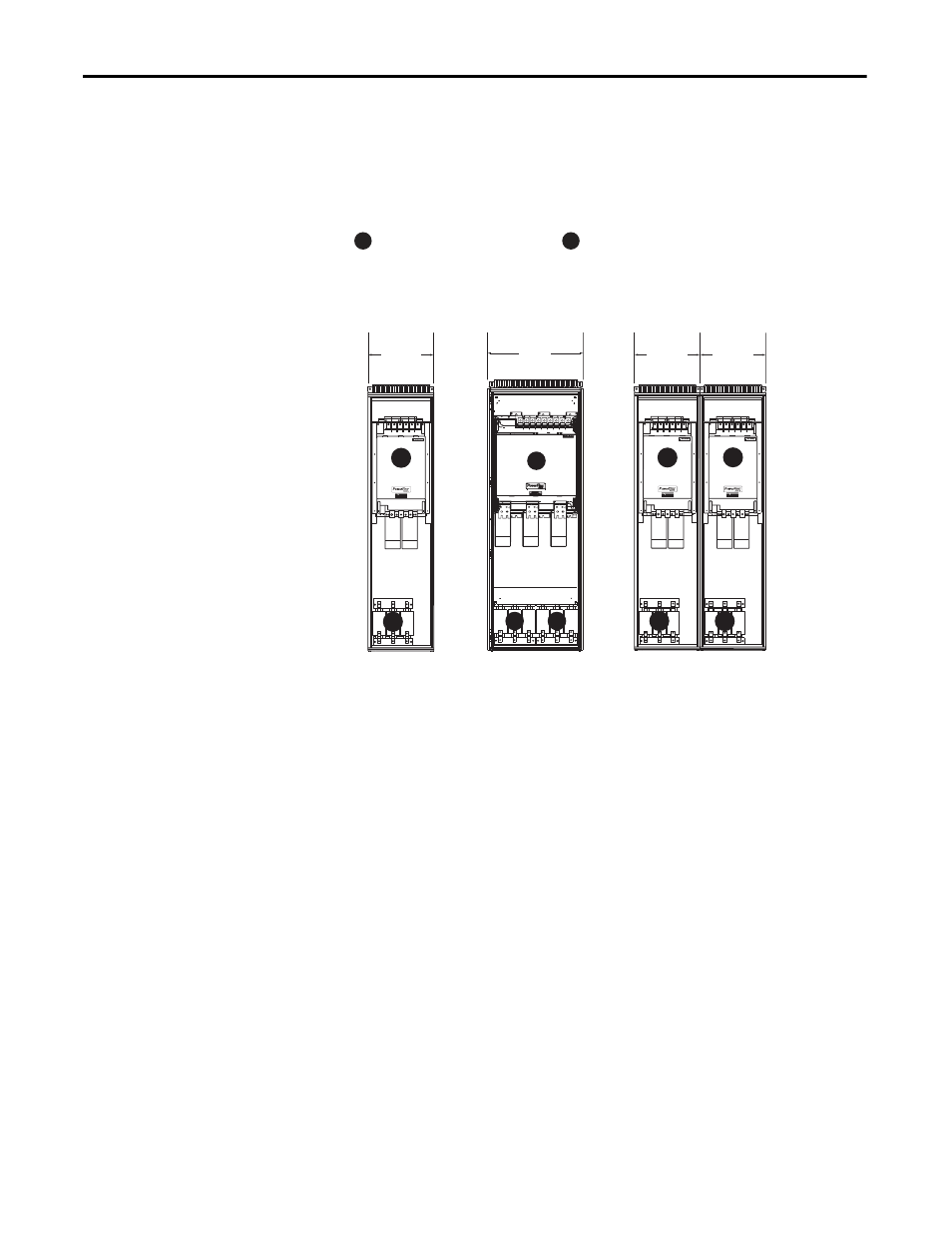
Frame 10…12 Component/Enclosure Configurations
The figures below are examples of typical installations based on the number of
components installed for a Frame 10…12 drive.
Figure 1 - Frame 10…12 Enclosure Configuration Examples
NFE Converter(s) and Inverter(s)
AC Choke
A
B
600
(23.6)
DANGER
DANGER
DC BUS CONDUCTORS AND CAPACITORS
OPERATE AT HIGH VOLTAGE. REMOVE POWER
AND WAIT 5 MINUTES BEFORE SERVICING
A
B
600
(23.6)
DANGER
DANGER
DC BUS CONDUCTORS AND CAPACITORS
OPERATE AT HIGH VOLTAGE. REMOVE POWER
AND WAIT 5 MINUTES BEFORE SERVICING
DANGER
DANGER
DC BUS CONDUCTORS AND CAPACITORS
OPERATE AT HIGH VOLTAGE. REMOVE POWER
AND WAIT 5 MINUTES BEFORE SERVICING
A
A
B
B
600
(23.6)
A
B
800
(31.5)
B
Dimensions are
in mm and (in.)
Frame 10
Frame 11
Frame 12