700s control connections – Rockwell Automation 20D PowerFlex 700S/700H Frames 10...14 IP00, NEMA/UL Open Power Structures User Manual
Page 42
42
Rockwell Automation Publication PFLEX-IN020C-EN-P - July 2013
PowerFlex 700S and 700H Frames 10...14 IP00, NEMA/UL Open Power Structures
700S Control Connections
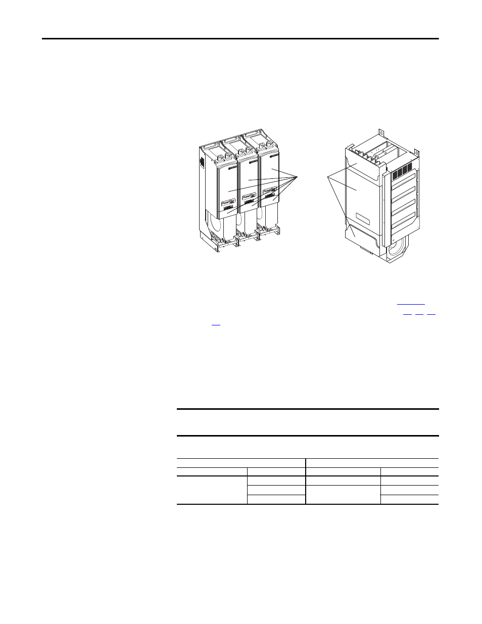
1. To access the ASIC board(s), remove the front protective cover(s) from
the power structure(s) as shown below.
2. Connect the 24V power supply cable and the fiber optic cables between
the Voltage Feedback Board and the Common Mode Filter and Fiber
Optic Interface or Fiber Optic Star Interface boards. Refer to
Table 22
below for cable designations and connection points and figures
28
,
29
,
30
and
31
for connector locations.
• Complete fiber optic cable connections after all electrical wiring has
been completed to avoid damage to the cables.
• Ensure that the fiber optic cables do not contact sharp objects that can
cause damage to the cables.
• The fiber optic cables have a minimum bending radius of 50 mm (2.0
in.).
Table 22 - Voltage Feedback Board Cable Designations
IMPORTANT
Verify correct cable/connector placement. Connecting the wires incorrectly
could damage components.
Connect this Point …
to this Point …
Location
Connector
Location
Connector
Voltage Feedback Board
J8
Common Mode Filter Board
J5
J5
Fiber Optic Interface or Fiber
Optic Star Interface Board
J7
J4
J6
Frames 13 and 14
Frames 10…12
(Frame 10 shown)
Protective
Covers