Channel transducer parameters – Rockwell Automation 1440-VAD02-01RA XM-123 Aeroderivative Module User Manual
Page 58
Publication GMSI10-UM003D-EN-P - May 2010
50
Channel Transducer
Parameters
The channel transducer parameters define the characteristics of the
transducers you will be using with the module. Use the parameters to
configure the transducer sensitivity, operating range, and power requirements.
There are two instances of the channel transducer parameters, one for each
channel.
TIP
The Channel LED will flash red when a transducer fault
condition exists on the channel even if you are not using
the channel. You can keep the Channel LED from flashing
red on unused channels by configuring the channel
transducer parameters as follows:
• Set the unused channel’s Fault High and Fault Low to
greater than zero and less than zero, respectively. For
example, set Fault High to +18 volts and set Fault Low
to -18 volts.
• Disable the unused channel’s transducer power by
clearing the Enable IEPE Power check box.
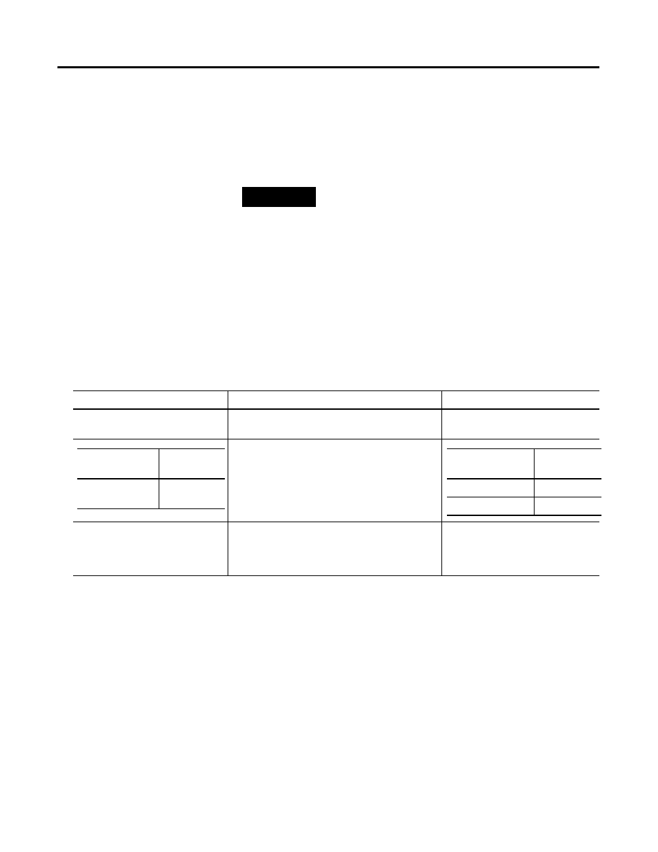
Channel Transducer Parameters
Parameter Name
Description
Values/Comments
Channel Name (XM Serial
Configuration Utility only)
A descriptive name to help identify the channel in
the XM Serial Configuration Utility.
Maximum 18 characters
Controls whether to provide standard accelerometer
(IEPE) power to the transducer.
Refer to Connecting the Transducer on page 27 for
wiring requirements.
Sensitivity
The sensitivity of the transducer in millivolts per
Eng. Unit.
The sensitivity value is included with
the transducer’s documentation or it
may be imprinted on the side of the
transducer.
XM Configuration
Utility
EDS File
Enable IEPE
Power
IEPE Power
XM Configuration
Utility
EDS File
Check = Enable
Enabled
Clear = Disable
Disabled