Important – Rockwell Automation 1440-VAD02-01RA XM-123 Aeroderivative Module User Manual
Page 43
Publication GMSI10-UM003D-EN-P - May 2010
35
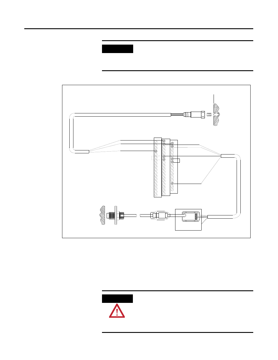
Figure 2.25 IEPE Accelerometer and Non-Contact Sensor Wiring
Connecting Two Accelerometers and a Non-Contact Sensor
Figure 2.26 shows the wiring of two IEPE accelerometers and a non-contact
sensor to the terminal base unit of the XM-123. The IEPE accelerometers are
wired to channel 1 and channel 2. The non-contact sensor is wired to the
tachometer input signal.
IMPORTANT
A jumper from terminal 5 to terminal 6 is required for
channel 1 buffered output. A jumper from terminal 22 to
terminal 21 is required for channel 2 buffered output. Refer
to Configuring Buffered Output Input Range on page 27.
TYPICAL WIRING FOR IEPE ACCELEROMETER AND
NON-CONTACT SENSOR TO XM-123 AERODERIVATIVE MODULE
Shield
Pin A - Signal
Pin B - Common
Cable shield not
connected at this end
0
16
22
6
21
Channel 1 Input Signal
Signal Common
5
37
SIG
-24
COM
17
1
Signal Common
Channel 2 Input Signal
-24V DC
13
Shield
S hield Floating
Isolated Sensor Driver
*
*
*Note: Jumpering terminal 5 to terminal 6
configures CH 1 buffer (-5V to +24V)
Jumpering terminal 21 to terminal 22
configures CH 2 buffer (-24V to +9V)
ATTENTION
You may ground the cable shield at either end of the cable.
Do not ground the shield at both ends. Recommended
practice is to ground the cable shield at the XM-123
terminal base and not at the transducer. Any convenient
Chassis terminal may be used (see Terminal Block
Assignments on page 18).