Rockwell Automation GV3000/SE AC Bookshelf Drive Hardware Ref, Installation, and Troubleshooting User Manual
Page 87
Compliance with Electromagnetic Compatibility Standards
C-3
C.3.1 Motor Leads
The motor leads must be run in continuous, rigid, conductive conduit,
continuously-screened armored cable, or equivalent. Note that the use of flexible
metal conduit, open wire, or wire in trays is not acceptable. Many flexible metal conduit
products have not been designed for RF containment and are not adequate to
maintain compliance.
All motor leads should have the same cross-sectional area. The maximum allowable
motor lead length from the drive to the motor is 250’ (76m).
A ground (earth) lead, equivalent in size to the motor leads, must be run with the
motor leads from the motor to the drive. Terminate this lead in the drive at the ground
terminal.
Proper glands must be used to terminate the motor conduit/cable. The gland must
secure the cable screen to the conductive surfaces of the drive and motor. A full 360
°
screen termination is preferred.
Follow all instructions supplied with the motor.
C.3.2 Grounding the Drive
Connect the drive/filter assembly to earth ground at the terminal provided (see figures
4.1 and 4.2. The ground wire should be sized per EN-60204-1, Part 5.2
1
, for copper
conductors and EN-60204-1, Part 8.2.2.2
2
, for non-copper conductors. European
Union standards require that the ground wire must be green/yellow according to
EN-60204-1, Part 15.2.2.
3
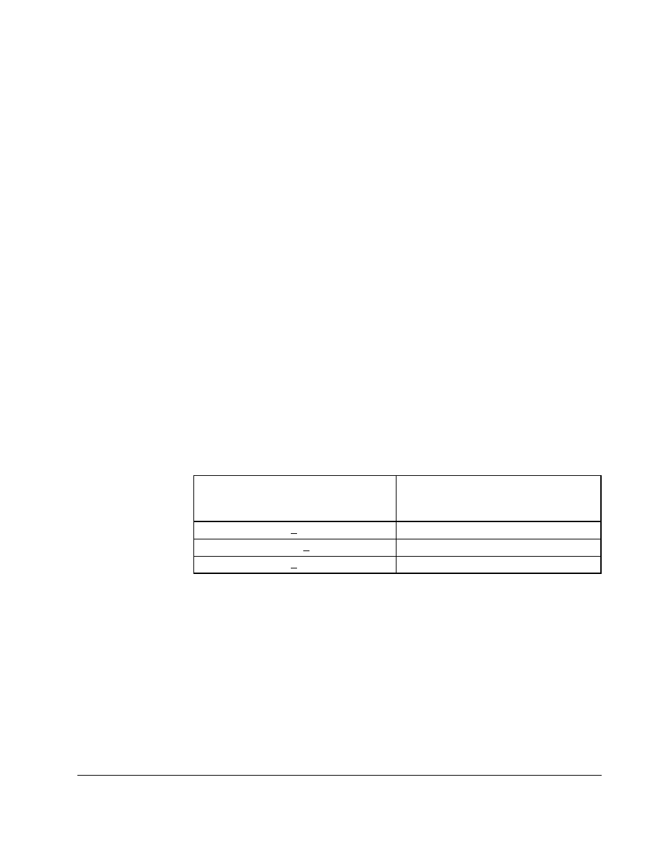
1
EN-60204-1, Part 5.2: Minimum Cross-Sectional Area of the External Protective
Copper Conductor
2
EN-60204-1, Part 8.2.2.2: Protective Conductors
Copper conductor should be used. If a material other than copper is used, its electrical
resistance per unit length should not exceed that of copper. Non-copper conductors
should not be less than 16 mm
2
in cross-sectional area.
3
EN-60204-1, Part 15.2.2: Identification of the Protective Conductor
For insulated conductors, the two-color combination of Green and Yellow should meet
the following criteria for any given 15 mm length: one of the colors should cover at
least 30% and no more than 70% of the surface, with the other color covering the
remainder of the surface.
Cross-Sectional Area of Phase
Conductors Supplying the Equipment
(S) (mm
2
)
Minimum Cross-Sectional Area of the
External Protective Conductor (mm
2
)
S < 16
S
16 < S < 35
16
S > 35
S/2