Wiring the signal and control i/o, 3 wiring the signal and control i/o – Rockwell Automation GV3000/SE AC Bookshelf Drive Hardware Ref, Installation, and Troubleshooting User Manual
Page 57
Wiring the Regulator Board Terminal Strip and the Output Relay Terminal Strip
7-7
7.3 Wiring the Signal and Control I/O
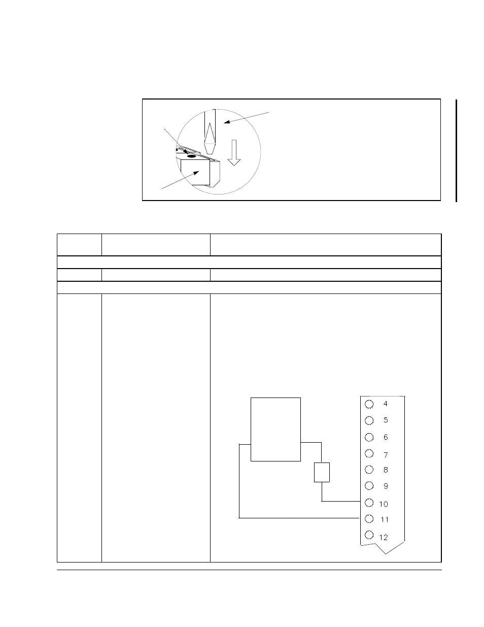
Wire the drive’s signal and control I/O to the terminal strip as shown in figure 7.4 and
table 7.7.
Figure 7.4 – Wiring the Terminal Strip - Detail
Use a small flat-head screwdriver.
Insert the screwdriver into the slot and
press and hold down while inserting the
wire into the corresponding hole.
Important: Using the incorrect tool and
exerting too much pressure may damage
the terminal strip.
Table 7.7 – Wiring Signal and Control I/O to the Regulator Board Terminal Strip
Terminal
Number
Description
Parameters/Wiring Connections
Wiring Encoder Inputs
4-9
Encoder Wiring
See section 7.2.
Wiring Analog Outputs
10
11
0-10 VDC or 4-20 mA
Analog Output Reference
Analog Output Return
The setting of parameter P.012 selects the terminal strip analog
output source (either speed or torque). Jumper J17 must also be
set. See figure 2.8.
The 4-20 mA current selection requires a power supply for
operation. The power must be sourced from an external 12 V
power supply.
Terminals 9 and 11 are internally connected.
+
-
+
-
-
Load
(Meter or Analog Input)
Terminal Strip
P/S
-
+
≤
500 Ohm
+
Terminal
Strip
Insert
wire