Rockwell Automation GV3000/SE AC Bookshelf Drive Hardware Ref, Installation, and Troubleshooting User Manual
Page 72
10-2
GV3000/SE AC Bookshelf Drive Hardware Reference, Version 6.06
To remove the cover:
a. Unscrew the attaching screw on the cover.
b. Lift the cover and carefully take it out of the heatsink as far as the flat
ribbon cable, which connects the display with the Regulator board, allows.
c. Use a screwdriver to slide the cable out of the connector on the Regulator
board to completely detach the cover.
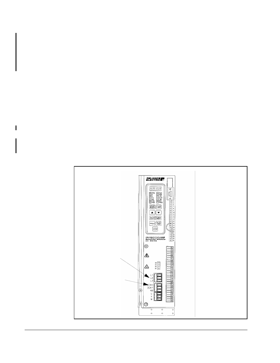
Step 4. Use a voltmeter to verify that there is no voltage at the drive’s AC input power
terminals (R/L1, S/L2, T/L3). Refer to figure 10.1, 10.2, or 10.3 for the
location of these terminals.
Step 5. Ensure that the DC bus capacitors are discharged. To check DC bus
potential:
a. Stand on a non-conductive surface and wear insulated gloves.
b. Use a voltmeter to measure the DC bus potential at the DC bus power
terminals ((-)45, (+)47) shown in figure 10.1, 10.2, or 10.3.
Step 6. 24 to 43 A drives only: Reattach the drive’s cover and front panel. Reconnect
all wiring to the face of the drive.
Important: When replacing the cover on 24 to 43 A drives, check that the display
cable is reconnected to the Regulator board. You will need to fold and
route the cable under the heatsink before replacing the cover.
Step 7. Reapply input power.
Figure 10.1 – DC Bus Voltage Terminals (2 to 15 Amp Drives)
DC Bus
Measuring Points
(-)45, (+)47
AC Input Power
Terminals
(L1, L2, L3)