Hapter – Rockwell Automation GV3000/SE AC Bookshelf Drive Hardware Ref, Installation, and Troubleshooting User Manual
Page 51
Wiring the Regulator Board Terminal Strip and the Output Relay Terminal Strip
7-1
C
HAPTER
7
Wiring the Regulator Board
Terminal Strip and the
Output Relay Terminal Strip
This chapter describes how to wire the Regulator board terminal strip for stop,
encoder feedback, and remote control signals. It also describes how to wire the output
status relays on the output relay terminal strip.
The signals available through the Regulator board terminal strip are shown in tables
7.1 to 7.4 and figures 7.1 and 7.2. Table 7.6 provides additional information.
Note that when the Control Source parameter (P.000) is set to remote (rE), the drive
will be controlled by the signals connected to the terminal strip. Refer to the
GV3000/SE Bookshelf Drive Software Start-Up and Reference manual for more
information on how parameter P.000 is used to specify where the drive is controlled
from.
The signals available through the output relay terminal strip are shown in table 7.5.
Table 7.7 provides additional information.
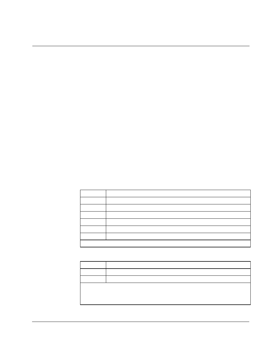
Table 7.1 – Encoder Connections (Regulator Terminals 4-9)
Terminal #
Signal
4
+15 VDC
5
Phase A
6
Phase A Not
7
Phase B
8
Phase B Not
9
Regulator Common
Notes: An encoder feedback device must be installed if FVC regulation is used.
Table 7.2 – Analog Output Connections (Regulator Terminals 10 and 11)
Terminal #
Signal
10
Analog Meter Output
11
Analog Output Return
Notes: The output of this terminal is either 0-10 VDC or 4-20 mA as determined by the
setting of jumper J17 on the Regulator board. The analog output must also be
programmed via parameter P.012 for an indication of speed and direction or percent of
torque.