Regulator board description, 6 regulator board description – Rockwell Automation GV3000/SE AC Bookshelf Drive Hardware Ref, Installation, and Troubleshooting User Manual
Page 20
2-6
GV3000/SE AC Bookshelf Drive Hardware Reference, Version 6.06
2.6 Regulator Board Description
Drive regulation is performed by a microprocessor on the Regulator board. See figure
2.6. Drive operation is adjusted by the parameters entered through the keypad. The
Regulator board accepts power circuit feedback signals and an external speed
reference signal, as well as data from an encoder that is attached to the motor when
set up for FVC regulation.
The Regulator board provides PWM gating signals to the IGBT power devices
. Based
on the output of the control loop, the regulator sends PWM gating signals through the
current feedback section of the Power board to the isolated gate drivers. These drivers
switch the Insulated Gate Bi-polar Transistors (IGBTs), producing a PWM waveform
that corresponds to the speed (FVC regulation) or frequency (V/Hz regulation)
reference. The IGBTs can be switched at either a 2, 4, or 8 kHz carrier frequency.
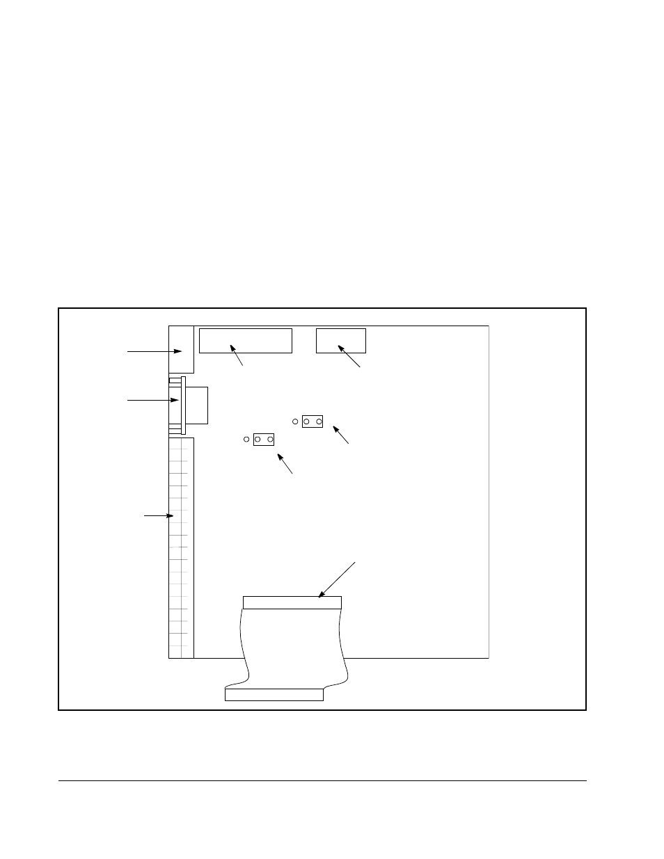
The Regulator board components are shown in figure 2.6 and described in the
following sections.
Figure 2.6 – Regulator Board Component Locations
J17
J4
V
Out
C
Out
V
In
C
In
OIM
Connector
(X7)
RS-232C
Port (X8)
Terminal Strip
Power Module
Feedback Connector
(X16)
Keypad/Display
Cable Connector
(X9)
Analog Output
Default: Voltage
Analog Input
Default: Voltage
Option Board Connector
(X3)
(X1)