Rockwell Automation WebPak 3000 DC Drives Hardware Reference, Installation and Troubleshooting User Manual
Page 83
Technical Specifications
A-5
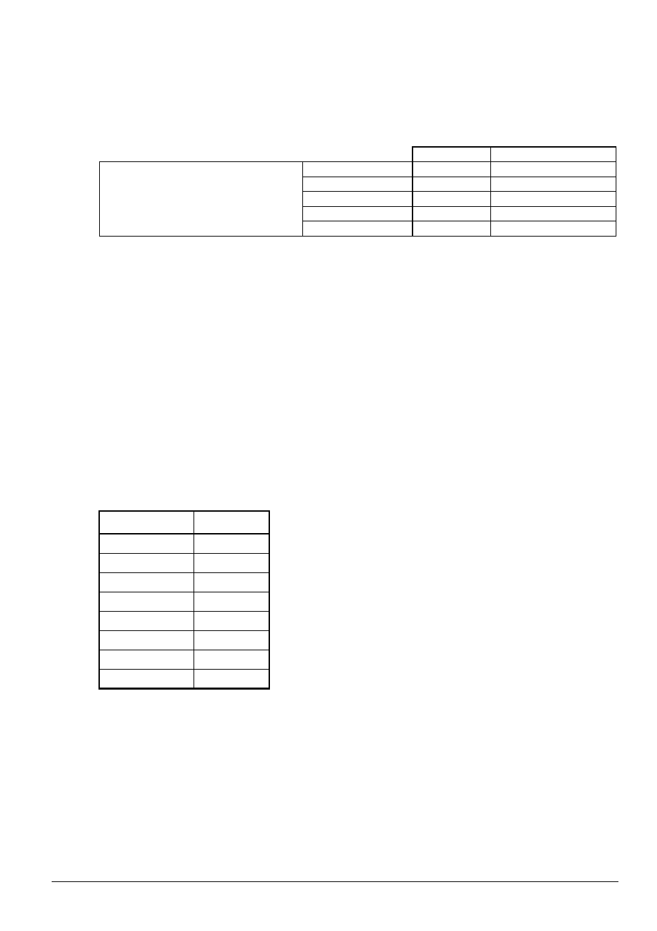
Analog Tachometer Feedback
Tach Voltage at Gear-in Speed .................................................................... 10 - 250 V DC
NOTE: J14 Jumper position and connection of DC-Tachometer must correspond.
Jumper J14
Jumper J11
Gear-in Speed Tach Volts
< 16 V
LOW
16
< 31 V
LOW
31/125
< 62 V
LOW
62/250
< 125 V
HI
31/125
< 250 V
HI
62/250
Analog Outputs:
The two metering analog outputs are available at regulator board terminals 24, 25 and 26.
Terminal 25 is the common connection for both output signals. The selected signals for both
meter outputs are averaged (filtered) over 100 msec to reduce meter fluctuations.
METER OUT 1 SELECT (P.404) corresponds to terminals 24 and 25 (default: CML
FEEDBACK). METER OUT 2 SELECT (P.405) corresponds to terminals 25 and 26 (default:
SPD LOOP FEEDBACK).
Refer to Appendix B, METER OUT 1 SELECT (P.404) and METER OUT 2 SELECT (P.405)
parameters, for additional drive test points that can be configured to source Meter Outputs 1
and 2.
Electrical Specifications:
Output Voltage..................................................................................................+/- 10 V DC
Maximum Load 4 milliamps
Drive Current Transformer Turns Ratio
Unit-Type
Tp/Tn
25 A
208
60 A
416
150 A
833
250 A
2000
450 A
3000
800 A
5230
1200 A,
8000
1600 - 2000 A
10500