Rockwell Automation WebPak 3000 DC Drives Hardware Reference, Installation and Troubleshooting User Manual
Page 81
Technical Specifications
A-3
Regulation (with 95% load change):
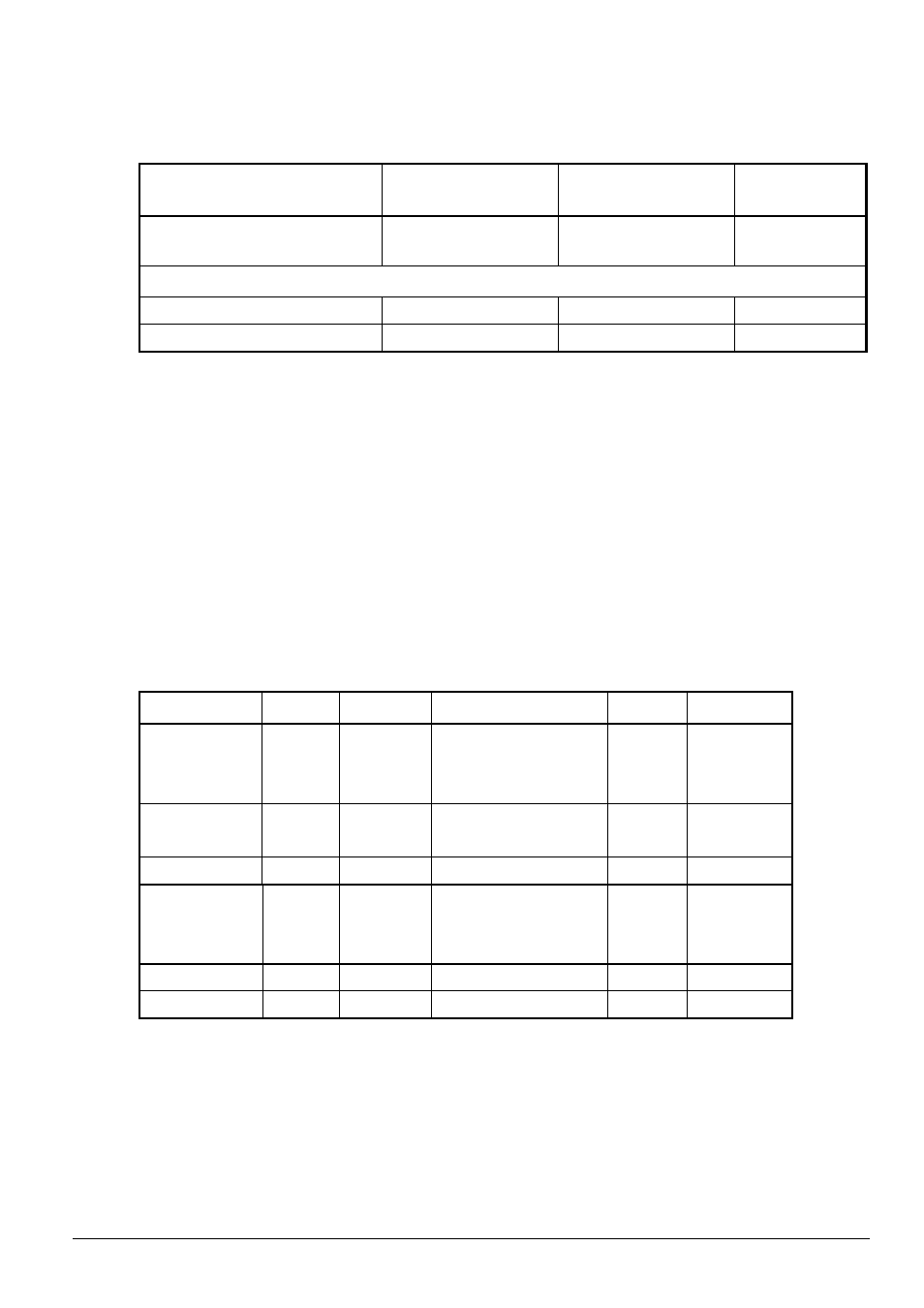
Table A.2 - Tachometer Speed Regulation
Regulation Arrangement
Speed Change with
95% Load Change
Speed Change from
All other Variables
Part Number
Armature Voltage Regulation
with IR Comp.
2-3 %
15%
Not applicable.
Closed Loop
with Analog tach
1%
2%
-
with Pulse tach 1)
0.01%
0.01%
762.70.00
1) Optional Pulse Tachometer Feedback kit required (See instruction manual 49’1343).
Speed Range:
Operator's Speed Adjustment ............................................................................. 0 to rated speed
Specification Speed Range ................................100:1 based on Gear In Speed and tachometer
Drive Efficiency:
Drive Only ...................................................................................... 98.6% (rated load and speed)
Drive and Motor ..........................................................................................................85% typical
Displacement Power Factor, Power Loss Pv and Output Current:
Power Factor: 88% typical (rated load & speed, decreasing linearly with speed)
Typical percent speed depends on motor operating speed and motor frame size.
Power Consumption at no load: see P
A
in Table A.3.
Table A.3 - Drive Specifications
Unit-Type
I
ad
I
anom
I
amax
I
F
P
A
P
v
(at I
a nom
)
25 A
25 A
20 A
30 A
4 A
60 VA
120 W
60 A
60 A
50 A
75 A
4 A
60 VA
210 W
150 A
150 A
125 A
187 A
10 A
85 VA
460 W
250 A
250 A
208 A
312 A
10 A
90 VA
715 W
450 A
450 A
375 A
562 A
10 A
90 VA
1215 W
800 A
800 A
667 A
1000 A
12 A
120 VA
2120 W
1200 A, 500V
1200 A
1000 A
1500 A
15 A *
400 VA
2680 W
1600 A, 500V
1600 A
1334 A
2000 A
15 A *
400 VA
3750 W
2000 A, 500V
2000 A
1667 A
2500 A
15 A *
400 VA
4600 W
1600 A, 575V
1600 A
1334 A
2000 A
15 A *
400 VA
3900 W
1600 A, 690V
1600 A
1334 A
2000 A
15 A *
400 VA
4100 W
I
ad
= Maximum continuous current without overload capability (I
ad
= 1.2 x I
a nom
)
I
a nom
= Nominal continuous current with overload capability 50% during 1 minute
every 10 minutes
I
a max
= Maximum current during 1 minute after 9 minutes operation with Ia nom
(I
a max
= 1.5 x I
a nom
)
I
F
= Field current without overload capability
* A maximum field current of 20 A is permitted, if the power unit blower is switched on
together with the motor field.