Rockwell Automation WebPak 3000 DC Drives Hardware Reference, Installation and Troubleshooting User Manual
Page 28
2-16
WebPak 3000 DC Drive Hardware Reference
2.5.7
Wire Optional Devices to the Drive
ATTENTION: Do not route signal wiring with power wiring in the same conduit. This
might cause interference with drive operation. Route signal wiring and power wiring
in separate conduits. Failure to observe this precaution could result in damage to,
or destruction of, the equipment.
ATTENTION: Connecting an external power source to any of the +24 volt
connections (terminals 1, 7, 11, and 14) on the Regulator board terminal strip will
damage the drive. DO NOT connect the external power source on the +24 volt
connections on the Regulator board terminal strip. Failure to observe this
precaution could result in damage to, or destruction of, the equipment.
ATTENTION: At very low input levels, noise or drift could cause analog input
polarity to change. This could result in damage to, or destruction of, the equipment.
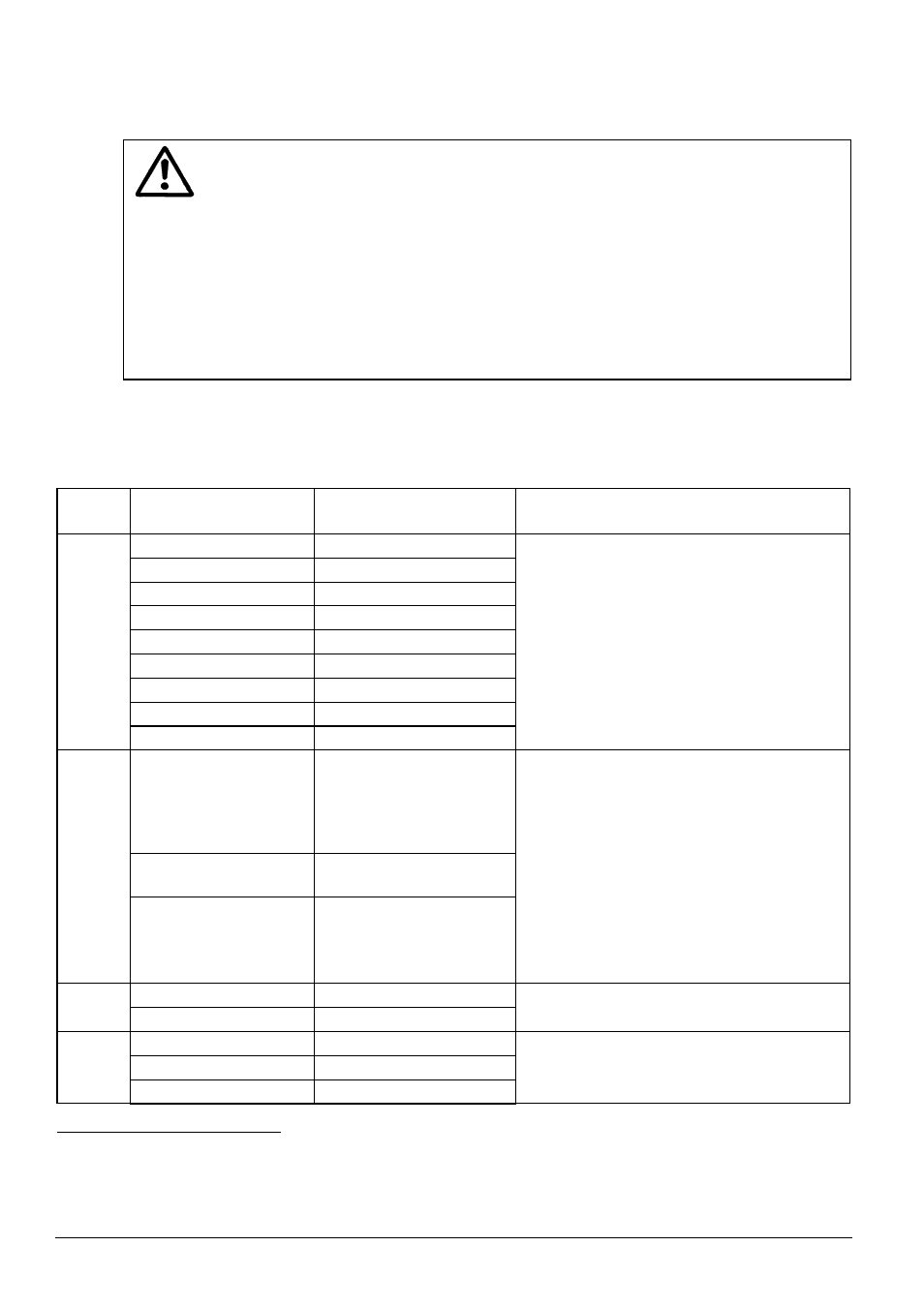
Refer to Figure 2.8b and the following Table 2.2 when wiring user devices to the drive.
Size and install all wiring in accordance with all applicable standards.
Table 2.2 - User Device Connections to the Regulator Board Terminal Strip
Signal
Type
User Device
Regulator Board
Terminal Connections
Description
Section Run
1 (+24V) and 2
Section Off
1 (+24V) and 3
Jog Fwd
1 (+24V) and 4
Jog Rev
1 (+24V) and 5
Underwind Enable
1 (+24V) and 6
Interlock
9 and 11 (+24V)
Fault/Alarm Reset
10 and 11 (+24V)
Slack Take-up
12 and 14 (+24V)
Logic
Inputs
Motor Thermostat
13 and 14 (+24V)
The logic input circuits can be powered
either from the internal +24 volt DC power
supply or from an external +24 volt DC
power source. The internal +24 volt DC
power supply is available at the Regulator
board terminal strip (see figure 2.8b).
If an external power source is used,
only the common must be connected to
24 V COM on the Regulator board
(terminal 15).
Diameter/Taper Range
or Trim Reference
•
High Side (+10V Isol)
•
Wiper (+)
•
Low Side (-)
16
17
18
Line Speed: (+)
(-)
19
20
Analog
Inputs
Tachometer (Analog):
High Range
2
Low Range
2
Common
2
21
22
23
These inputs are converted at 12 bits plus
sign.
Analog Output 1
24 and 25 (common)
Analog
Outputs Analog Output 2
25 (common) and 26
The signals for both analog outputs can be
averaged (filtered) over 100 ms.
Running (Indicator)
27 and 28
Alarm (Indicator)
29 and 30
Logic
Outputs
No Fault (Indicator)
31 and 32
The logic output circuits are normally-open
(when de-energized) relay contacts.
1
Analog tachometer must be rated between 18 and 200 Volts/1000 RPM. The output voltage must not exceed 250 V when the motor is
rotating at the value set for the GEAR IN SPEED parameter. To calculate the output voltage:
Tachometer voltage at GEAR IN SPEED = GEAR IN SPEED/1000 x ANALOG TACH VOLTS/1000
2
When the maximum tach voltage is 62 VDC or lower, use terminals 22 and 23 to connect the analog tachometer. When the maximum tach
voltage is between 63 and 250 VDC, use terminals 21 and 23 to connect the analog tachometer.