Connections to 2801-jmb interface – Rockwell Automation 5370 Color CVIM Communications Manual User Manual
Page 34
Chapter 3
Using Local I/O
3–14
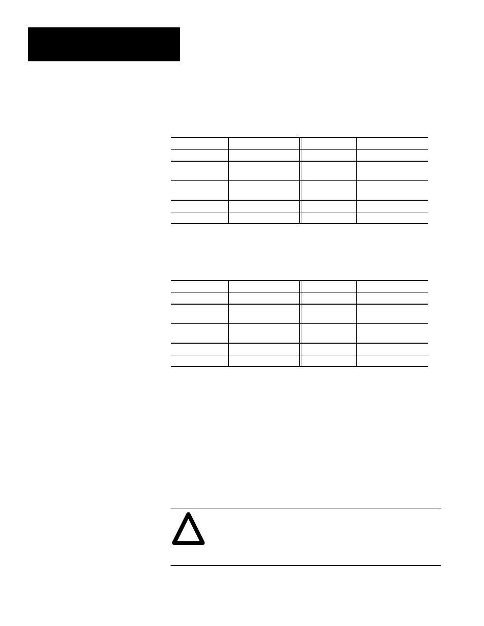
Table 3.D
I/O Interface Box (Catalog No. 2801–N27):
RS–232 Port A Connector with Color CVIM Module
Pin Number
Function
Pin Number
Function
1
No Connection
6
No Connection
2
RXD (Receive
Data: RS–232A)
7
+ 5V DC*
3
TXD (Transmit
Data: RS–232A)
8
No Connection
4
+ 5V DC*
9
No Connection
5
Ground (Signal)
*Not to be used to power external devices.
Table 3.E
I/O Interface Box (Catalog No. 2801–N27):
RS–232 Port B Connector with Color CVIM Module
Pin Number
Function
Pin Number
Function
1
No Connection
6
No Connection
2
RXD (Receive
Data: RS–232B)
7
+ 10V DC*
3
TXD (Transmit
Data: RS–232B)
8
No Connection
4
+ 10V DC*
9
No Connection
5
Ground (Signal)
*Not to be used to power external devices.
The 2801–JMB interface board is designed for direct edge connection to the
I/O Interface Box, Catalog Nos. 2801–N21, –N27.
If you intend to use the 2801–JMB board and the I/O Interface Box, you will
need to know the relationship between the discrete I/O line numbers and the
LED numbers, the optic–isolator type, and the terminal block screws
numbers on the 2801–JMB board. These are shown in the figure and table
that follows.
To power the JMB logic components, you must connect an
external +5VDC power supply to the (+) and (–) terminal
screws shown on the board layout that follows.
ATTENTION:
!
Color CVIM Module I/O
Interface Box Connections
(cont’d)
Connections to
2801–JMB Interface