Configuration blocks 2 & 3 – Rockwell Automation 5370 Color CVIM Communications Manual User Manual
Page 203
Appendix D
Configuration Data
D–4
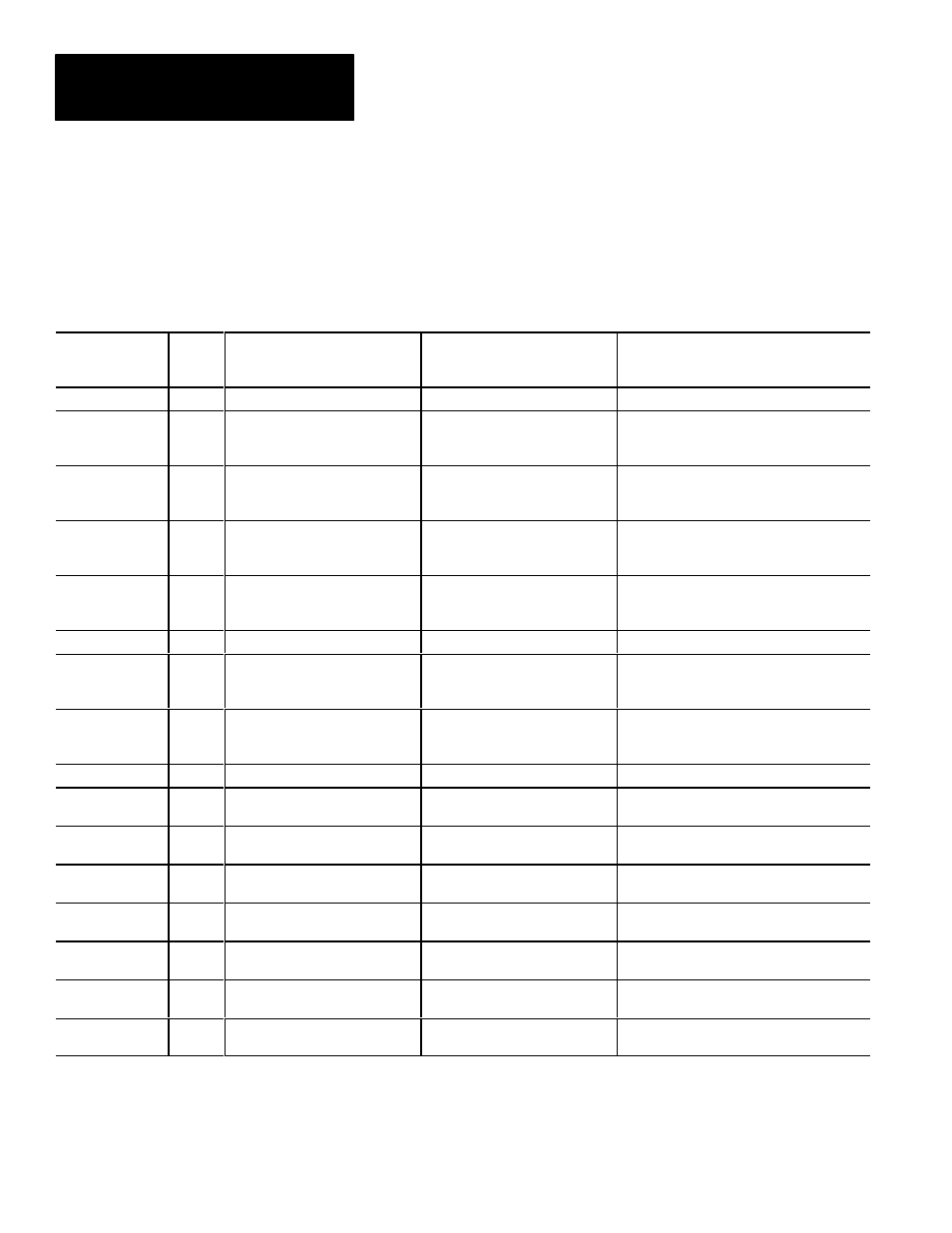
Tables D.2 and D.3 show the function of each word in the camera definition
configuration blocks.
Table D.2
Configuration Block #2 – Camera Definition
Remote I/O
& RS–232
Word #*
Bit #
Definition
Usage
Notes
0
0–15
Block Transfer Signature
1
0–9
10–15
Reserved
High Reference of Red Converter
0 = Minimum Value
. . .
63 = Maximum Value
2
0–9
10–15
Reserved
High Reference of Green Converter
0 = Minimum Value
. . .
63 = Maximum Value
3
0–9
10–15
Reserved
High Reference of Blue Converter
0 = Minimum Value
. . .
63 = Maximum Value
4
0–7
Light Probe Status
0 = Disabled
1 = Same Field
2 = Next Field
4
8–15
Reserved
5
0–15
Light Probe X Location
16 = Minimum Value
. . .
504 = Maximum Value
6
0–15
Light Probe Y Location
8 = Minimum Value
. . .
232 = Maximum Value
7–16
0–15
Reserved
17
0–15
Fail Range High for Red Channel
(Integer)
Words 17 and 18 represent a 16(bit).16(bit)
fixed point decimal value.
18
0–15
Fail Range High for Red Channel
(Fraction)
19
0–15
Fail Range Low for Red Channel
(Integer)
Words 19 and 20 represent a 16 (bit). 16 (bit)
fixed point decimal value.
20
0–15
Fail Range Low for Red Channel
(Fraction)
21
0–15
Warning Range High for Red
Channel (Integer)
Words 21 and 22 represent a 16 (bit).16 (bit)
fixed point decimal value.
22
0–15
Warning Range High for Red
Channel (Fraction)
23
0–15
Warning Range Low for Red
Channel (Integer)
Words 23 and 24 represent a 16 (bit). 16 (bit)
fixed point decimal value.
Configuration Blocks 2 & 3