Plc-5 programming, Program action – Rockwell Automation 1794-XXXX FLEX I/O High-Density Analog Modules User Manual
Page 79
Publication 1794-UM062A-EN-P - September 2012
Module Programming 71
Program Action
At power-up in RUN mode, or when the processor is switched from PROG to
RUN, the user program enables a block transfer read. Then it initiates a block
transfer write to configure the module and send data values.
Thereafter, the program continuously performs read block transfers and write
block transfers.
PLC-5 Programming
The PLC-5 program is very similar to the PLC-3 program with the following
exceptions:
• block transfer enable bits are used instead of done bits as the conditions on
each rung.
• separate block transfer control files are used for the block transfer
instructions.
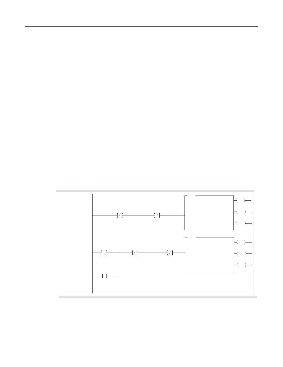
PLC-5 Family Sample Program Structure for a 1794-IE8 Module
Program Action
At power-up in RUN mode, or when the processor is switched from PROG to
RUN, the user program enables a block transfer read. Then it initiates a block
transfer write to configure the module if the power-up bit is set.
TIP
You must create the data file for the block transfers before you enter
the block transfer instructions
EN
BTR
BLOCK TRANSFER READ
RACK:
GROUP:
SLOT:
DATA FILE:
2
1
0
N13:0
LENGTH:
CONTROL:
9
N12:0
Pushbutton
N12:0
15
DN
ER
BTR Enable Bit
EN
BTW
BLOCK TRANSFER WRITE
RACK:
GROUP:
SLOT:
DATA FILE:
2
1
0
N13:20
LENGTH:
CONTROL:
1
N12:5
DN
ER
Power-up Bit
1
B13:8
15
1
Power-up bit included in Series B modules only.
1
2
15
N12:5
BTW Enable Bit
CONTINUOUS:
N
CONTINUOUS:
N
N12:5
15
BTW Enable Bit
15
N12:0
BTR Enable Bit