Rockwell Automation 1794-XXXX FLEX I/O High-Density Analog Modules User Manual
Page 66
Publication 1794-UM062A-EN-P - September 2012
58
Data Tables
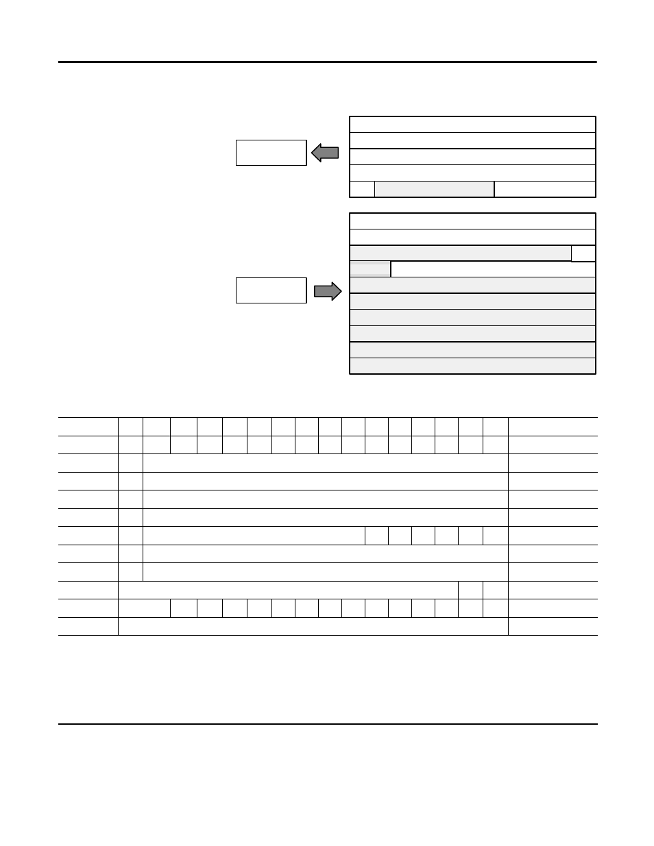
Memory Map – 1794-IE4XOE2/B and 1794-IE4XOE2XT Analog Combo Module
Decimal Bit 15
14
13
12
11
10
09
08
07
06
05
04
03
02
01
00
Size
Octal Bit
17
16
15
14
13
12
11
10
07
06
05
04
03
02
01
00
Read/Write Words
S
Analog Value Channel 0
Read word 1
S
Analog Value Channel 1
Read word 2
S
Analog Value Channel 2
Read word 3
S
Analog Value Channel 3
Read word 4
PU
Not used – set to 0
W1 W0 U3
U2
U1
U0
Read word 5
S
Analog Data – Output Channel 0
Write word 1
S
Analog Data – Output Channel 1
Write word 2
Not used – set to 0
OE1 OE0
Write word 3
Not used
C5
C4
C3
C2
C1
C0
0
0
F5
F4
F3
F2
F1
F0
Write word 4
Not used – set to 0
Write word 5…10
Where:
PU = Power up bit – included in series B modules only.
W = Diagnostic bits for current output wire broken or load resistance high. (Not used on voltage outputs.)
U = Underrange bits for 4…20 mA inputs
S = Sign bit (in 2’s complement)
OE = Output enable bits (bit 00 corresponds to output 0, bit 01 corresponds to output 1, and so on.
C = Configure select bit
F = Full range bit
Module Image
I/O Image
Input Data Channel 0
Input Data Channel 1
Input Data Channel 2
Input Data Channel 3
Output Data Channel 0
Output Data Channel 1
Underrange & Diag.
Not used
Not used
Not used
Not used
Not used
Not used
Not used
Full Range and Configure Select
Not used
Input Size
Output Size
0 to 4 Words
0 to 5 Words
Read
Write
OE
PU
46068