Rockwell Automation 1794-XXXX FLEX I/O High-Density Analog Modules User Manual
Page 70
Publication 1794-UM062A-EN-P - September 2012
62
Data Tables
S
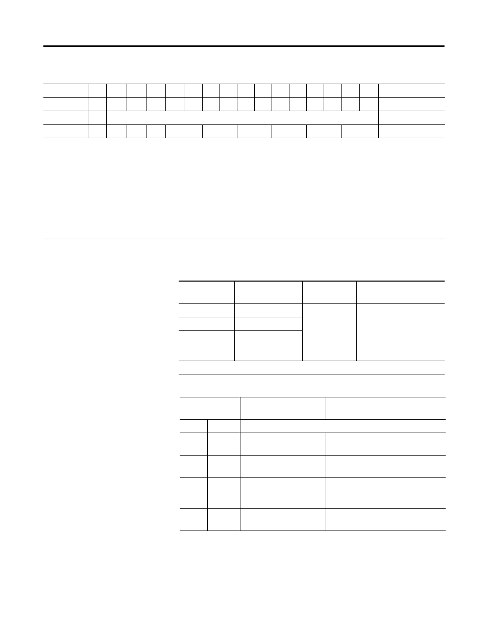
Analog Data – Output Channel 3
Write word 4
QS
0
0
0
CAB
C89
C67
C45
C23
C01
Write word 5
Where:
PU = Power up bit
FP = Field power fault
GF = General fault
NU = Not used
Wx = Wire off (x = associated channel)
Rx = Out of range (x = associated channel)
EN = Enable outputs
S1/S0 = Safe state source - When EN = 0, these bits indicate source of safe state output.
WR = Wire-off reset
QS = Quick step bit - allows input filter to be reduced during rapid signal changes.
Cxx = Channel Configuration (xx = associated channel pair)
Memory Map – 1794-IE8XOE4 Analog Combo Module
Decimal Bit 15
14
13
12
11
10
09
08
07
06
05
04
03
02
01
00
Size
Octal Bit
17
16
15
14
13
12
11
10
07
06
05
04
03
02
01
00
Read/Write Words
Range Selection Bits – 1794-IE8XOE4 Analog Combo Module
Range
Out of Range
Range Setting
Cxx Channel
Configuration
-10…+10V DC
1< -10.0V or > 10.0V
Set bits for each
channel pair
00 = off
01 = 0…20 mA
10 = 4…20 mA
11 = ±10V
C01 for channels 0 and 1
C23 for channels 2 and 3
C45 for channels 4 and 5
C67 for channels 6 and 7
C89 for channels 8 and 9
CAB for channels 10 and 11
4…20 mA
<4.0 mA or >20.0 mA
0…20 mA
<0.0 mA or >20.0 mA
Where:
Cxx = associated channel pair.
Safe State Selection Bits – 1794-IE8XOE4 Analog Combo Module
S1/S0 Safe State
Select Source
Safe State Mode
Safe State Output Behavior
S1
S0
0
0
Safe State value is in the
output words
Outputs use Safe State value
0
1
Reserved (Safe State value
is in the output words)
Reserved (Outputs use Safe State
value)
1
0
Clear/Reset the outputs,
based on range selected
+10V range – Output set to 0V
4…20 mA range – Output set to 4 mA
0…20 mA range – Output set to 0 mA
1
1
Hold output at its present
level
Outputs Hold Last State