Rockwell Automation 1794-XXXX FLEX I/O High-Density Analog Modules User Manual
Page 31
Publication 1794-UM062A-EN-P - September 2012
Install Your FLEX I/O Module 23
Connect Wiring Using a 1794-TB3S, 1794-TB3T, 1794-TB3TS, or
1794-TBN Terminal Base Unit
1. Connect individual input/output wiring to numbered terminals on the
0…15 row (A) for 1794-TB3S, 1794-TB3T and 1794-TB3TS, or on row
(B) for the 1794-TBN as indicated in the following tables.
2. Connect channel common/return to the associated terminal on row (A)
or row (B) for the 1794-TB3S, 1794-TB3T and 1794-TB3TS, or on
row (C) for the 1794-TBN. For input devices requiring terminal base
power, connect the channel power wiring to the associated terminal on
row (C).
3. Connect any signal wiring shields to functional ground as near as possible
to the module.
1794-TB3T or -TB3TS only: Connect to earth ground terminals
C-39…C-46.
4. Connect the +V DC power to terminal 34 on the 34…51 row (C) and -V
common/return to terminal 16 on the (B) row.
5. If daisychaining +V power to the next terminal base, connect a jumper
from terminal 51 (+V DC) on this base unit to terminal 34 on the next
base unit.
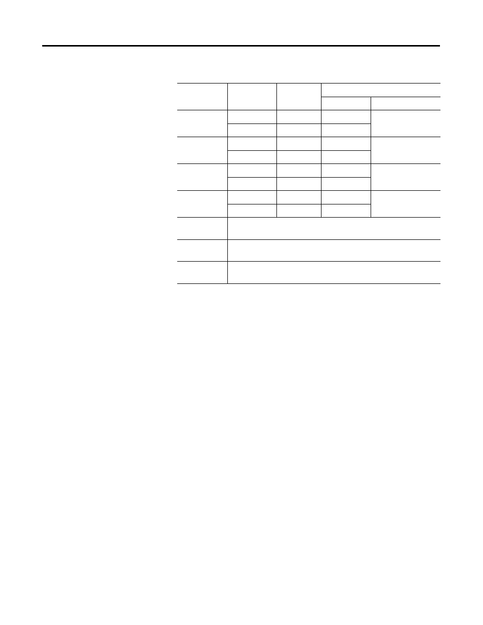
Output 0
Current
I8
B-19
C-37
Voltage
V8
B-20
Output 1
Current
I9
B-21
C-39
Voltage
V9
B-22
Output 2
Current
I10
B-27
C-46
Voltage
V10
B-28
Output 3
Current
I11
B-29
C-48
Voltage
V11
B-30
-V DC Common 1794-TB3G and 1794-TB3GS – Terminals C-35 and C-51 are internally
connected in the terminal base unit.
+V DC Power
1794-TB3G and 1794-TB3GS –Terminals C-34 and C-50 are internally
connected in the terminal base unit.
Chassis
Ground (Shield)
1794-TB3G and 1794-TB3GS – Terminals B-16, B-33, C-38, C-40
through C- 45, and C-47 are internally connected to chassis ground.
Wire Connections for 1794-TB2, and 1794-TB3 using the 1794-IE8XOE4 Module
Channel
Signal Type
Label
Marking
1794-TB3G or 1794-TB3GS
Input/Output
Common Terminal