Rockwell Automation 1794-XXXX FLEX I/O High-Density Analog Modules User Manual
Page 11
Publication 1794-UM062A-EN-P - September 2012
Overview of FLEX I/O and Your Analog Module 3
How FLEX I/O Analog
Modules Communicate
with Programmable
Controllers
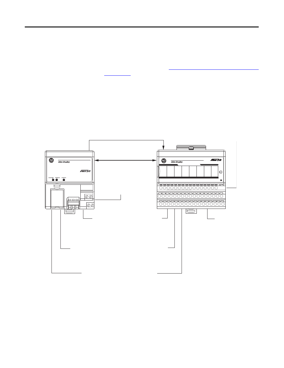
The adapter/power supply transfers data to the module (block transfer write) and
from the module (block transfer read) using BTW and BTR instructions in your
ladder diagram program. These instructions let the adapter obtain input values
and status from the module, and let you send output values and establish the
module’s mode of operation. The
Typical Communication Between the Adapter
figure describes the communication process.
Typical Communication Between the Adapter and a Module
ADAPTER
ACTIVE
FAULT
LOCAL
FAULT
24VDC
POWER SUPPLY
RIO ADAPTER
1794-ASB
IN 0
IN 2
IN 4
IN 6
IN 1
IN 3
IN 5
IN 7
TC RTD INPUT 8 CHANNEL
3
1794-IRT8
PWR
F
F
F
F
F
F
F
F
45316
The adapter transfers your configuration data.
FlexBus
External devices transmit
analog signals to the module.
The module converts
analog signals into binary
format and stores these
values until the adapter
requests their transfer.
The adapter receives data
from the modules and stores
it in the data table.
The adapter module determine that the
transfer was made without error and
input values are within specified range.
Your ladder program can use and/or move the data (if valid)
before it is written over by the transfer of new data in a
subsequent transfer.
1
4
5
6
2
3
New configuration data can be sent to the
module any time during operation.
7
1794-ACN15
1794-ACNR15
1794-ADN
1794-AENT
1794-AENTR
MicroLogix
1794-ASB
1794-APB
Adapter
1794-AENT shown