Rockwell Automation 1794-XXXX FLEX I/O High-Density Analog Modules User Manual
Page 65
Publication 1794-UM062A-EN-P - September 2012
Data Tables 57
1794-IE4XOE2 Series B and 1794-IE4XOE2XT – 4 Input 2 Output Analog Combo
Module Image Table Mapping
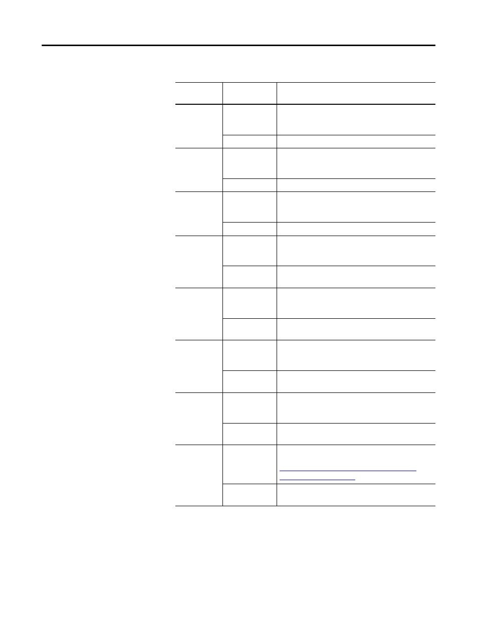
Write word 6
Bits 00…14
(00…16)
Channel 5 analog data – 12-bit left justified two's
complement number; unused lower bits are zero;
4…20 mA uses all 16 bits.
Bit 15 (17)
Channel 5 analog data sign bit.
Write word 7
Bits 00…14
(00…16)
Channel 6 analog data – 12-bit left justified two's
complement number; unused lower bits are zero;
4…20 mA uses all 16 bits.
Bit 15 (17)
Channel 6 analog data sign bit.
Write word 8
Bits 00…14
(00…16)
Channel 7 analog data – 12-bit left justified two's
complement number; unused lower bits are zero;
4…20 mA uses all 16 bits.
Bit 15 (17)
Channel 7 analog data sign bit.
Write word 9
Bits 00…07
Channel 8 analog data – 12-bit left justified two's
complement number; unused lower bits are zero;
4…20 mA uses all 16 bits.
Bit 08…15
(10…17)
Channel 8 analog data sign bit.
Write word 10 Bits 00…07
Channel 9 analog data – 12-bit left justified two's
complement number; unused lower bits are zero;
4…20 mA uses all 16 bits.
Bit 08…15
(10…17)
Channel 9 analog data sign bit.
Write word 11 Bits 00…07
Channel 10 analog data – 12-bit left justified two's
complement number; unused lower bits are zero;
4…20 mA uses all 16 bits.
Bit 08…15
(10…17)
Channel 10 analog data sign bit.
Write word 12 Bits 00…07
Channel 11 analog data – 12-bit left justified two's
complement number; unused lower bits are zero;
4…20 mA uses all 16 bits.
Bit 08…15
(10…17)
Channel 11 analog data sign bit.
Write word 13 Bits 00…11
(00…13)
Configuration – Set range for each channel pair. For
more information on range selection bits, see
Table Range Selection Bits – 1794-OE12 Analog
Output Module on page 55
Bits 12…15
(14…17)
Not Used.
Word/Bit Descriptions – 1794-OE12 Analog Output Module
Word
Decimal Bit
(Octal Bit)
Definition