Chapter summary – Rockwell Automation 1794-XXXX FLEX I/O High-Density Analog Modules User Manual
Page 34
Publication 1794-UM062A-EN-P - September 2012
26
Install Your FLEX I/O Module
Chapter Summary
In this chapter you learned how to install the FLEX I/O analog module in an
existing programmable controller system and how to wire to a terminal base unit.
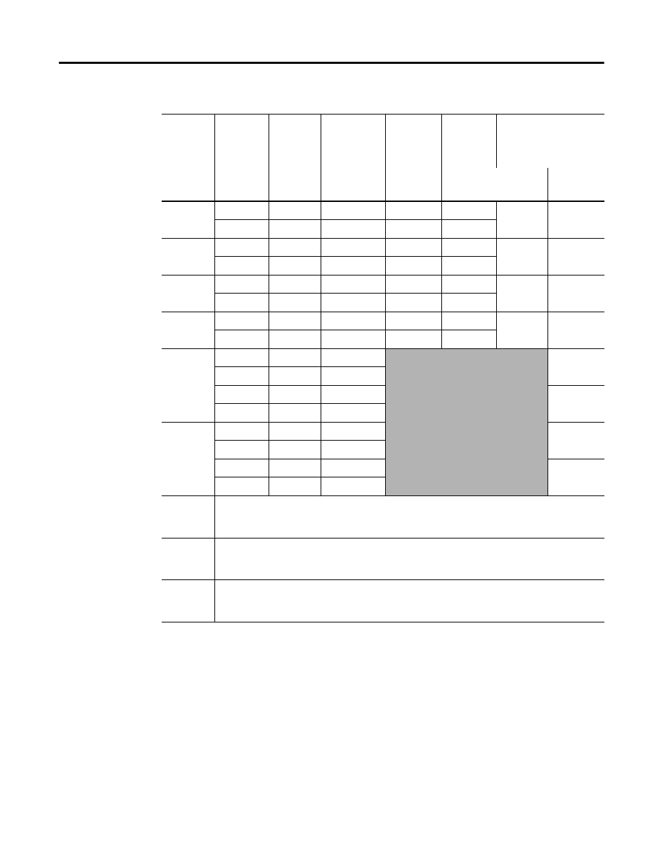
Wire Connections for 1794-TB3S, 1794-TB3T and 1794-TB3TS using the 1794-IE4XOE2XT Module
Channel
Signal
Type
Label
Markings
1794
-TB3S,
-TB3T,
-TB3TS
1794-TB3S
1794-TB3S 1794-TB3T,
1794-TB3TS
Input/Output
Terminal
(1)
Power
Terminal
(2)
Common Terminal
Shield
Input 0
Current
I
A-0
C-35
B-17
B-17
C-39
Voltage
V
A-1
C-36
B-18
Input 1
Current
I
A-2
C-37
B-19
B-18
C-40
Voltage
V
A-3
C-38
B-20
Input 2
Current
I
A-4
C-39
B-21
B-21
C-41
Voltage
V
A-5
C-40
B-22
Input 3
Current
I
A-6
C-41
B-23
B-23
C-42
Voltage
V
A-7
C-42
B-24
Output 0
Current
I
A-8
C-43
Voltage
RET
A-9
V
A-10
C-44
RET
A-11
Output 1
Current
I
A-12
C-45
Voltage
RET
A-13
V
A-14
C-46
RET
A-15
24V DC
common
1794-TB3S – Terminals 16…33 are internally connected in the terminal base unit.
1794-TB3T, 1794TB3TS- – Terminals 16, 17, 19, 21, 23, 25, 27, 29, 31 and 33 are internally
connected in the terminal base unit.
+24V DC
power
1794-TB3S – Terminals 34…51 are internally connected in the terminal base unit.
1794-TB3T, 1794-TB3TS – Terminals 34, 35, 50 and 51 are internally connected in the terminal
base unit.
Chassis
ground
(Shield)
1794-TB3T, 1794-TB3TS – Terminals 39…46 are internally connected to chassis ground.
(1)
A-9, 11, 13 and 15 are internally connected in the module to 24V DC common.
(2)
Use when transmitter requires terminal base power.