Explicit messaging ladder logic program, Example data tables – Rockwell Automation 2755-SNx Adaptascan Bar Code Readers User Manual
Page 247
12–26
Communicating with a PLC-5 Processor on a DeviceNet Network using Explicit Messaging
Publication 2755-6.8
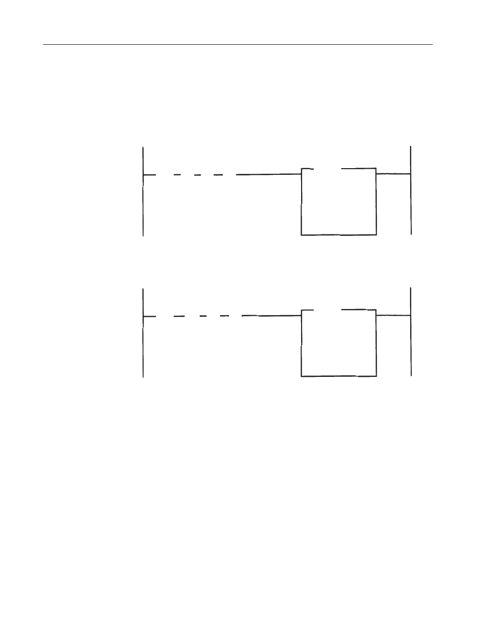
Explicit Messaging Ladder Logic Program
This section provides the explicit message ladder logic program and
data monitor results.
Rack
Module
Group
0
00
0
BTW
B3
0
]
[
Enable Rung B3:0 to initiate the download process to the AdaptaScan. File N20:0
contains the APM command. The DeviceNet address being written to, in this example,
is 10 or 0AH. The N7 inputs are needed if the code from page 12–5 is used.
N7:0
15
]
[
/
N7:100
15
]
[
/
Ctrl Block
Data file
Length
Continuous
B3
2
[
]
ONS
N7:200
N20:0
64
N
B3
1
]
[
After BTW is complete, initiate the the BTR statement to retrieve the response
code. The N7 inputs are needed if the code from page 12–5 is used.
N7:0
15
]
[
/
N7:100
15
]
[
/
Rack
Module
Group
0
00
0
BTR
Ctrl Block
Data file
Length
Continuous
N7:150
N25:0
64
N
B3
3
[
]
ONS
Note: You can write code to continuously change the TXID for the
next transaction. Refer to page 12–21 for information regarding
formatting the explicit message transaction block
Example Data Tables
Address
Data = Hex Code (matchcode download of 0300 data)
N20:0
0101
000C
1003
00CE
0001
0003
0004
3330
3030
Address
Response File (good
response)
N25:0
0101
900C
Address
Data = Hex Code (Turn on LED 1)
N20:0
0101
0008
1003
00C9
0002
0003
0001