Related publications, Connecting to the devicenet network, Connecting a power supply to the reader – Rockwell Automation 2755-SNx Adaptascan Bar Code Readers User Manual
Page 142
9–2
Communicating with an SLC 5/03 Processor on a DeviceNet
t
Network
Publication 2755-6.8
Related publications include:
Publication
Description
2755-837
AdaptaScan Bar Code Readers User Manual
2755-838
AdaptaScan Software User Manual
1787-6.5.3
DeviceNet Manager Software Manual
1747-6.5.2
1747-SDN DeviceNet Scanner Configuration Manual
In addition, you may want to refer to the SLC 500 Hardware and
Software User Manuals.
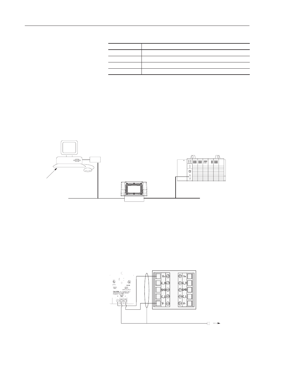
The following illustration shows the nodes of the DeviceNet
master/slave network. You must terminate the first and last node in
the network. Refer to the 1747-SDN DeviceNet Scanner
Configuration Manual (Publication No. 1747-6.5.2) for more
information regarding user termination information.
Computer
1770-KFD
DeviceNet
Interface Box
AdaptaScan
Bar Code Reader
SLC 5/03 Processor
1747-SDN DeviceNet Scanner
1787-MGR DeviceNet Manager Software
SLC 500 Advanced Programming Software
2755-ASN AdaptaScan Software
Node 62
DeviceNet Trunk Cable
Node 1
DeviceNet Trunk Cable
Node 3
The following illustration shows how to connect a 2755-PW46 or
-PW47 power supply to a single bar code reader.
Use a shielded cable (Belden 9316 recommended) to make the
connections. Connect the shield to the ground screw on the reader’s
wiring base.
V-
24V+
Ground Screw
on Wiring Base
Reader
2755-PW46
Power Supply
Note: Use a termination switch for DeviceNet in the wiring base for
the end of the network.
Related Publications
Connecting to the
DeviceNet Network
Connecting a Power
Supply to the Reader