App a - scanner mode i/o map, Discrete input data, Appendix a – Rockwell Automation 1756-RIO ControlLogix Remote I/O Communication Interface Module User Manual User Manual
Page 129: Scanner mode i/o map, Ices a, Appendix
Publication 1756-UM534B-EN-P - November 2010
129
Appendix
A
Scanner Mode I/O Map
This section describes how the data gets mapped to the ControlLogix data for
scanner mode.
When you map any part of a rack to produced/consumed tag data, the
structure that gets mapped is for the entire rack number. For example, if rack 1
consists of I/O groups 0 and 1 (a quarter rack), the entire structure for rack 1
is mapped when you map the rack. Similarly, if a rack is made up of several
partial racks, mapping any one of those partial racks maps the structure for the
entire rack.
Discrete Input Data
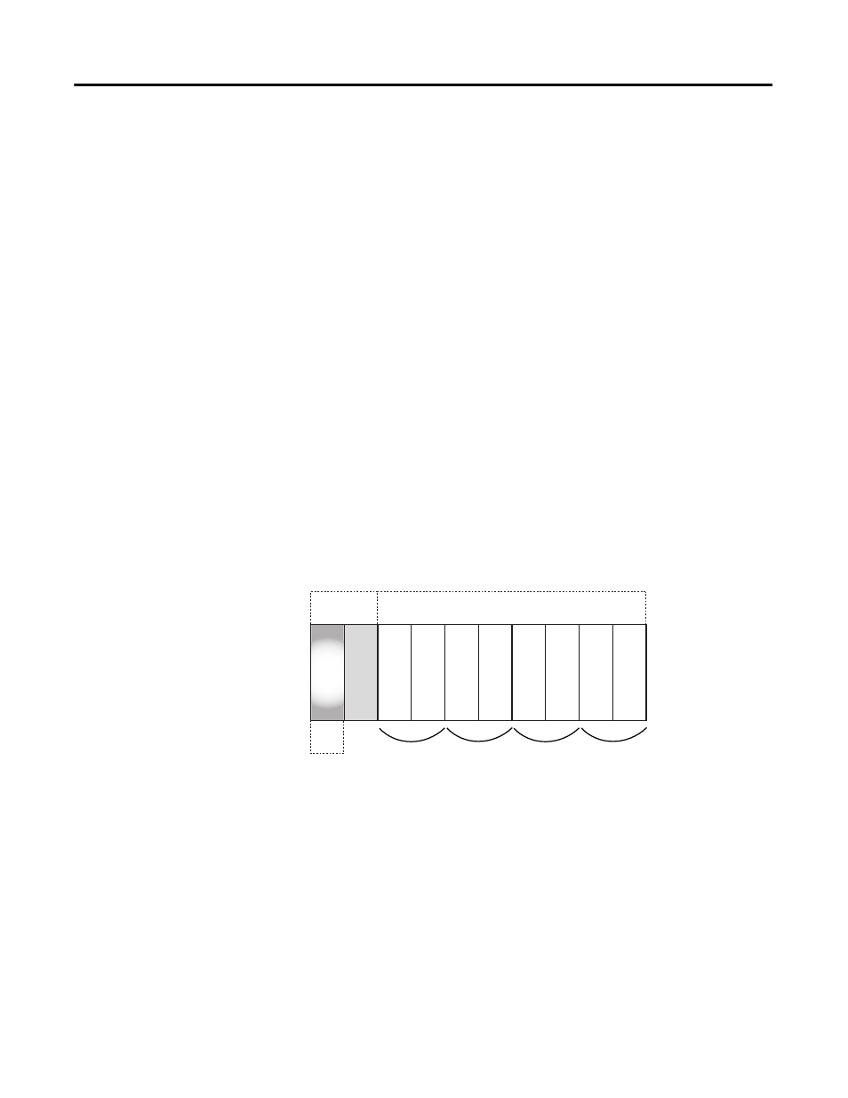
In scanner mode, the discrete read structure for a rack consists of two status
words and eight words of discrete input data.
Discrete Read Structure-Input
Only bits 0…3 of the first word of status data are used. They consist of error
bits that are set if there is a communication error with a partial rack. Bit 0
corresponds to a rack that starts at I/O group 0; bit 1 corresponds to a rack
that starts at I/O group 2, and so on.
The error bit is 1 if there is an error scanning the rack, or if the rack is
inhibited; otherwise, the bit is 0.
Words 2…9 contain the discrete input data for the rack. Words 2 and 3
contain the data for I/O groups 0 and 1 (first 1/4 rack), words 3 and 4 contain
the data for I/O groups 2 and 3 (second 1/4 rack), and so on.
0 1 2 3 4 5 6 7 8 9
Status Codes and
Error Codes
Discrete Input Data
1st
16-bit
Word
44817