G-file configuration – Rockwell Automation 1746-BLM Blow Molding Module Installation Instructions User Manual
Page 27
Blow-molding Module 27
Publication 1746-IN014B-EN-P - January 2001
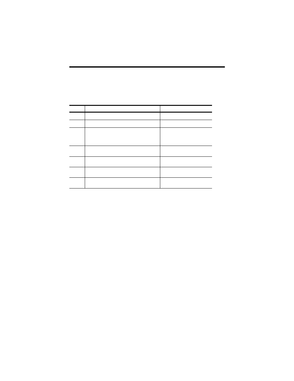
G-file Configuration
The module requires software-configured selections in G file words 1-4 for axes
1-4, respectively. All four axes have identical structures:
Bit
Purpose
Selection
00
axis operation is time based
(1)
(2)
(1)
Bits 00 and 01 must be set to opposite states, else a fault occurs.
(2)
When setting up a continuous extrusion machine, consider this:
Select time-based operation for each axis to be used.
Specify zero for the independent axis.
Select an SLC-generated or externally-generated start-of-drop synchronization input, depending
on your machine requirements.
Select SLC-generated or module-generated synchronization output, depending on your machine
requirements.
Specify a user profile size of 256 points
(unless SLC memory space requires fewer points)
0 = disabled, 1 = enabled
01
axis operation is position based (if set, see
(3)
)
(3)
When setting up an accumulator machine, consider this:
Select position-based operation for each axis to be used.
Specify a number between 0 and 3 for each independent axis.
Select an SLC-generated start-of-drop synchronization input, since this feature is unused in
position-based mode (This lets the SLC processor use the input for other purposes).
Select SLC-generated or module-generated synchronization output, depending on your
application’s requirements.
Specify a profile size of 256 points
(unless SLC memory space requires fewer points)
0 = disabled, 1 = enabled
02-04
mandrel will follow:
- accumulator axis number:
- SLC profile via output image file:
enter bit code, such as
000 for axis 1, 001 for axis 2, 010
for axis 3, 011 for axis 4
100
05
axis synch input source (see note 3)
0 = from module DIN input
1 = from SLC output image
06
axis synch output source (see note 3)
0 = from module DOUT
1 = from SLC output image
07
SP and PV range
0=-32k to +32k
1= 0 to +10k
08-15
axis profile size (modulo 256) range of 0-255 (see
note 3)
bit code for number of setpts