Rockwell Automation 1758-RTU202 DataSite Hardware User Manual User Manual
Page 43
Publication 1758-UM001D-EN-P - June 2011
Wiring the Controller
43
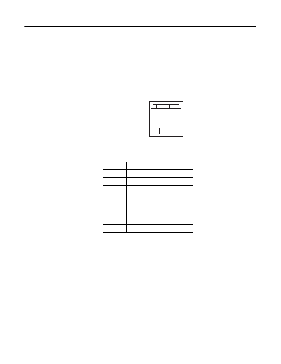
Ethernet RJ-45 connector
The receptacle (P8) of the RJ-45 module is the connection terminal of
Ethernet. The receptacle of the RJ-45 module matches its 8-pin connector and
adopts a 10BASE-T Unshielded Twisted Pair. Pins 1 and 2 are used for
transmitting data, pins 3 and 6 are used for receiving data, and pins 4, 5, 7 and
8 are spare pins.
Ethernet RJ-45 connector
The RJ-45 port definition of Ethernet is as follows:
Ethernet cable
The Ethernet cable connecting the RJ-45 connector of the DataSite controller
to the PC is a 10BASE-T standard non-shielded twisted pair. The following
figure shows the array mode of the Ethernet cable.
Pin assignments of Ethernet connector
Pin
Function
1
Transmit data TD+
2
Transmit data TD-
3
Receive data RD+
4
NC
5
NC
6
Receive data RD-
7
NC
8
NC
1 2 3 4 5 6 7 8
44627