Rockwell Automation 1758-RTU202 DataSite Hardware User Manual User Manual
Page 37
Publication 1758-UM001D-EN-P - June 2011
Wiring the Controller
37
All of the peripheral connecting wires of RS232 should be shielded cables. The
shielding layer should be connected with the shell at one point; the metal shell
of DB-9P is a good grounding point.
There are several methods to connect RS232 port with DTE and DCE (data
communication equipment). The simplest connection method is three-wire
system connection: RXD, TXD and signal ground.
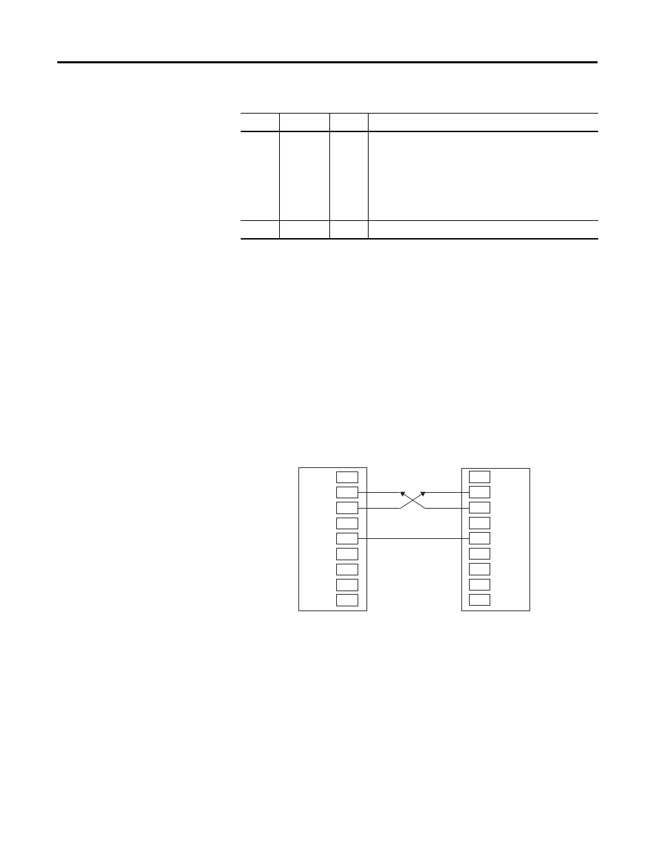
RS232 DTE to RS232 DTE without Handshaking
The following figure has shown a standard connection mode between RS232
port and DTE without handshaking signal.
Pin 8
CTS
Input
EFFECTIVE for the communication port to transmit data.
When the attached device does not provide this signal,
the controller stays at an EFFECTIVE level.
When the attached device does provide this signal, it
must set CTS to EFFECTIVE to allow the controller to
transmit data.
CTS LED is lighting for an EFFECTIVE level.
Pin 9
—
NC
This pin is not connected.
Pin Assignments for RS232 Connector (Continued)
Pin
Function Type
Description
CTS
RTS
GND
DTR
TXD
RXD
DCD
RS232 (DTE)
1
2
3
4
5
6
7
8
9
CTS
RTS
GND
DTR
TXD
RXD
DCD
DTE
1
2
3
4
5
6
7
8
9
44696