Using surge suppressors, Screw-cage clamp terminal block – Rockwell Automation 1758-RTU202 DataSite Hardware User Manual User Manual
Page 26
Publication 1758-UM001D-EN-P - June 2011
26 Wiring the Controller
Using Surge Suppressors
Because of the potentially high current surges that occur when switching
inductive load devices, such as motor starters and solenoids, the use of some
type of surge suppression to protect and extend the operating life of the
controllers output field effect transistors (FETs) or contacts is required.
Switching inductive loads without surge suppression can significantly reduce
the life expectancy of the output channel. By adding a suppression device
directly across the coil of an inductive device, you prolong the life of the
output or relay contacts. You also reduce the effects of voltage transients and
electrical noise from radiating into adjacent systems.
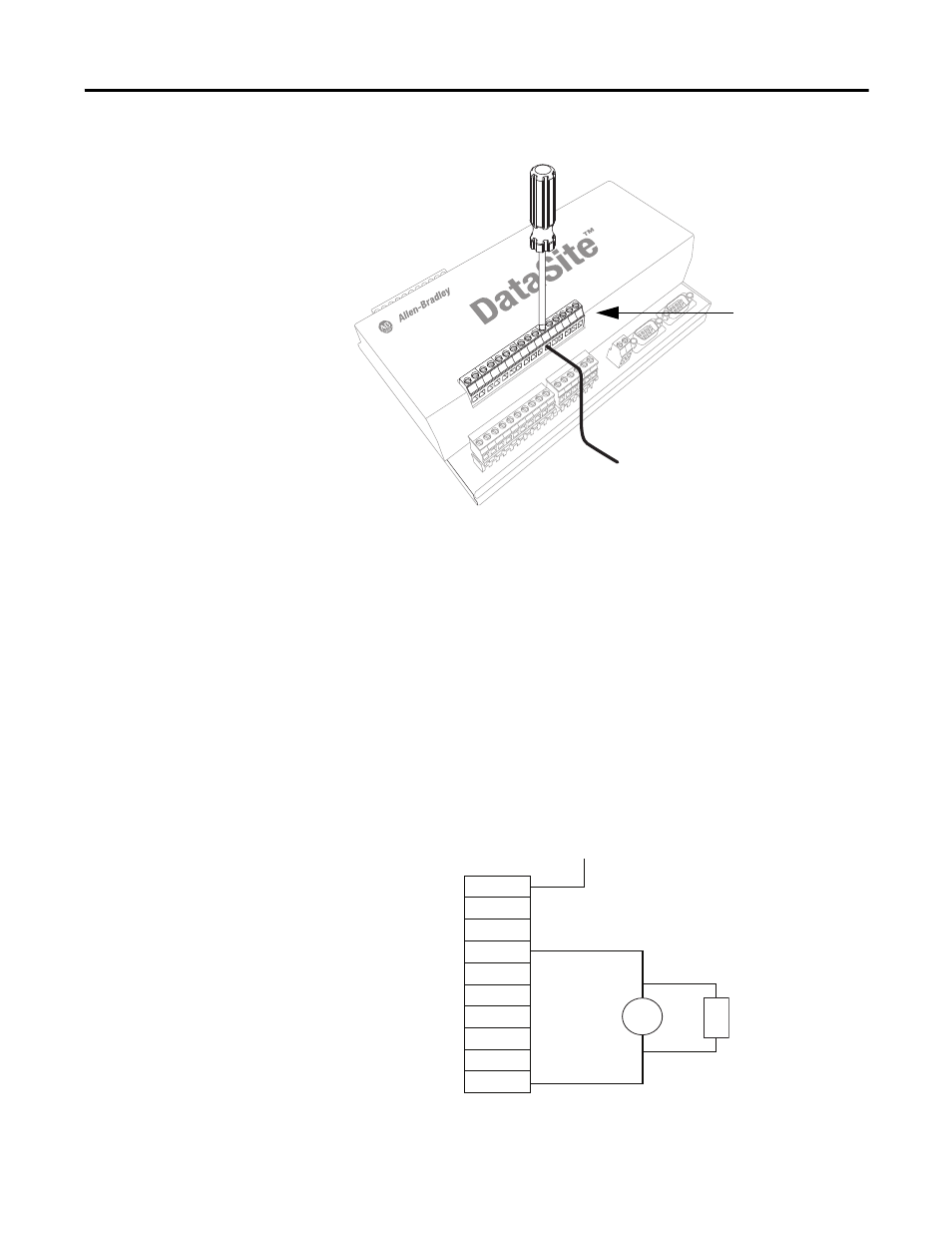
The following diagram shows an output with a suppression device. We
recommend that you locate the suppression device as close as possible to the
load device.
30
1
2
3
31
32
33
34
35
36
37
38
39
40
41
42
43
44
45
4
5
6
7
8
9
10
11
12
13
14
15
16
18
17
Screw-cage clamp
terminal block
44756
+DC or L1
Suppression device
DC COM or L2
AC or DC
outputs
Load
VAC/DC
Out 0
Out 1
Out 2
Out 3
Out 4
Out 5
Out 6
Out 7
COM